TITAN25T Assembly Guides
Uncrating Guide
0: Uncrating/Unboxing
The Titan 25T base unit is delivered fully assembled on a singular skid. An in depth description of what is inside is provided here. Please use this as a reference for the rest of the assembly.

Main Box
- (1) Fully assembled Titan 25T
- (1) Foot Pedal
- (1) Power Cord
- (1) Tooling Sub Box
- (1) Punch Clamp Box
1: Add-on Unboxing
At the time of purchase, if any Titan add-ons were selected, they will be shipped nested within the Titan 25T boxing.

Backguage Add-on Box
- METAL TUBE WELDMENTS SUB BOX
- (1) LINEAR BEARING AND LEAD SCREW SUB BOX
- (1) DRAG CHAIN
- (1) MISC PARTS SUB BOX
- (1) BACKGUAGE ELECTRONICS BOX
- (1) MISC HARDWARE BOX
Material Support Tray Add-on Box
- (1) LINEAR BEARING AND RAIL ASSEMBLY
- (2) SUPPORT BRACKET WELDMENTS
- (2) MISC PARTS SUB BOX
Press Brake Stand Add-on Boxes(2)
- (1) LH CAST SIDE SUPPORT
- (1) RH CAST SIDE SUPPORT
- (1) MATERIAL STORAGE TRAY
- (1) ADJUSTABLE CASTER BOX
- (1) PRESS BRAKE STAND FOOT SUB BOX
- (2) STAND DIAGONAL BRACE
Titan Lift Plate Add-on Package
- (2) TITAN LIFT PLATES
- (2) HARDWARE SUB BAG
Leveling Foot Kit Add-on Box
- (4) LEVELING FEET
- (4) LEVELING FOOT MOUNT
- (1) HARDWARE BAG
2. Removing the Shipping Support Arms
The first step in removing Titan from the pallet is to remove the support arms and angle iron from the unit.
Parts
- None
Hardware
- None
Tools
- (2) ½” Box End Wrenches
- (1) 9/16” Socket Wrench
- (1) Pry Bar (Optional)

Instructions
Note: Titan 25T arrives bolted to a metal bracing to ensure safe shipping. This bracing must be removed prior to moving and operating the Titan 25T. Failure to remove the metal structure prior to operation can damage the Titan 25T.
- Using two ½” Box End Wrenches, loosen and remove all bolts highlighted in magenta on the shipping bracing from both sides. Then, using a 9/16” Socket Wrench, remove the nuts securing the angle iron to the Titan 25T Pallet. Remove bracing from the pallet.
Note: If removal of the bolts that attach the angle iron to the bottom of the Titan 25T proves to be a challenge, using a pry bar to slightly elevate the Titan off pallet will remove vertical loading on the bolts for easy removal.
3: Preparing to Lift The Titan 25T
The second step to remove the Titan 25T from its pallet is to prepare the designated lift points.
Parts
- (2) Titan Lift Plate
Hardware
- (4) 5/16-18 x 1 ¾ Hex Head Flange Bolt
- (4) 5/16-18 Flange Nut
Tools
- None

Instructions
WARNING SYMBOL: TITAN 25T LIFT POINTS
- The Titan 25T comes equipped with two hydraulic cylinder fairings that cover one of the designated lift points. To gain access to the lift point, remove the fairings from their magnetic connectors by pulling them vertically off of the Titan 25T. Set aside for reinstallation at a later time.
- Install and orient the Titan Lift Plates with the provided fasteners as shown.
INFO SYMBOL : LIFTING EQUIPMENT
- Do you own or have access to a forklift to lift the Titan 25T? See the forklift lifting section
- Do you own or have access to a shop crane rated for 1000 lbs to lift the Titan 25T? See the Shop Crane/Engine Hoist Section
4: Maneuvering the Titan on the Pallet
Before lifting with an Engine Hoist/Shop Crane, the Titan must be maneuvered so that the Hoist can be properly positioned.
Parts
- None
Hardware
- None
Tools
- Angle Grinder or Bolt Cutter

Instructions
WARNING SYMBOL: PERSONAL PROTECTIVE EQUIPMENT
- Using an angle grinder, grind down the two studs protruding from the pallet shown.
Parts
- None
Hardware
- None
Tools
- None

Instructions
Parts
Hardware
Tools
- Pry Bar (24in+ Recommended)

Instructions
- Locate a pry bar to assist with maneuvering the Titan 25T. We recommend a length of 2 ft minimum for easy maneuverability.
- Position the end of the pry bar such that it sits in the relief between the feet of one of the uprights as shown.
- With the pry bar positioned as shown, begin by prying Titan slightly off the pallet (~0.125”) until both feet are raised up.
- Next, sweep the pry bar to the right such that Titan moves in an arced path. If done correctly, the foot closest to the pry bar should now be closer to the far end of the pallet and Titan will be sitting at an angle on the pallet.
- On the same side of the unit, position the pry bar next to the opposite foot and repeat the process outlined in steps B2-B4, but sweep the pry bar in the opposite direction.
WARNING SYMBOL: FALLING/TIPPING HAZARD
Parts
Hardware
Tools
- Pry Bar (24in+ Recommended)

Instructions
- Continue to pry and walk the Titan until the upright closest to the pallet’s perimeter is within 1.5”- 2” from the edge.
5: Lifting with a Shop Crane/Engine Hoist
The next step is to utilize your shop crane to access the final lift point.
Parts
- (1) Titan Lift Plate (Optional Purchase)
Hardware
- (2) 5/16 x 1 ¾ Hex Head Flange Bolts
- (2) 5/16 Flange Nuts
Tools
- Shop Crane/Engine Hoist
- Pry Bar

Instructions
WARNING SYMBOL: LIFTING EQUIPMENT
- With the Lift Plate or Substitute lifting equipment in place, position the hook of your shop crane so that the hook can be attached to the lift plate as shown.
- Lift the side of the Titan approximately 0.125” off the pallet. The majority of Titan’s weight will still be supported by the pallet on the other side of the unit.
- Next, using the same pry bar method to walk the Titan 25T to the edge of the pallet in the maneuvering step, begin walking Titan off of the pallet. You will need to pry and then move the shop hoist backwards to walk the Titan off of the pallet.
- Continue to walk the Titan 25T until the feet still on the pallet approach the edge of the plywood surface.
WARNING SYMBOL: FALLING/TIPPING HAZARD
Parts
Hardware
Tools
- Shop Crane/Engine Hoist

Instructions
- Titan 25T should be positioned similar to the image provided above once fully walked to one side of the pallet.
Parts
- (1) Titan Lift Plate (Optional Purchase)
Hardware
- (2) 5/16 x 1 ¾ Hex Head Flange Bolts
- (2) 5/16 Serrated Lock Nuts
Tools
- Shop Crane/Engine Hoist
- Blocking Material

Instructions
- Using blocking material, fill the void under the Titan 25T that is suspended in air as shown. Blocking material should be approximately 5 ¾” tall to maintain a surface even with the top of the pallet.
- Slowly lower the suspended Titan 25T until the full weight of the unit is distributed between the blocking material and the pallet.
- Remove the Shop Crane/Hoist from the hook point.
Parts
Hardware
- 9/32 Trade Size Lifting Chain
- (Optional) Chain Shackles
Tools
- (1) Shop Crane/Engine Hoist

Instructions
- Span the lifting chain between the slots found on the Titan Lift Plates.
- Reposition your shop crane such that the hook point rest at the midpoint of your chain span as shown and connect the chain to the hook.
- Lift your Titan 25T fully off of the pallet.
WARNING SYMBOL: CRUSH HAZARD
Parts
- None
Hardware
- None
Tools
- (1) Shop Crane/Engine Hoist

Instructions
- With Titan off the pallet, you may position the unit in your shop where desirable.
6: Lifting with a Forklift
The next step is to prepare and lift the Titan 25T with a forklift.
Parts
- (2) Titan Lift Plate (Optional Purchase)
Hardware
- 9/32 Trade Size Lifting Chain (4ft Length)
- (Optional) Chain Shackles
Tools

Instructions
- Span the lifting chain between the slots found on the Titan Lift Plates or between the 5/16-18 Bolts with oversized washer.
- Prior to lifting, ensure the chain is in line with the slot features of the Titan Lift Plate or ~3.5” back from the screen side of the electronic enclosure as shown.
- Begin lifting Titan 25T off of the pallet.
WARNING SYMBOL: CRUSH HAZARD
Parts
Hardware
- 9/32 Trade Size Lifting Chain (4ft Length)
- (Optional) Chain Shackles
Tools

Instructions
- With Titan off of the pallet, you may position the unit in your shop where desirable.
Material Tray Support Assembly Guide
1: Preparing The Handbrakes
The first step is to mate the linear brakes with the brake mount brackets.
Parts
- (2) Linear Rail Handbrake
- (2) Brake Mount Bracket
Hardware
- Socket Head Cap Screw, M4 x 0.7mm x 10mm
Tools
- 3 mm Hex Key

Instructions
- Locate both Linear Rail Hand Brake Assembly and Brake Mount Brackets.
- Orient the Hand Brakes such that the lever faces down and the brake mount bracket extends to the left of the handbrake.
- Using the fasteners shown, loosely secure the brake mount bracket to the linear handbrake.
- Set aside for later use.
2: Swingarm Assembly
The next step in the assembly process is to assemble the guide block swingarms.
Parts
- (2) Track Bearing Swingarm Assembly
Hardware
- (2) Hex Head Cap Screw, 10-24 x ¾
Tools
- None

Instructions
- Locate a Track Bearing Swingarm Assembly.
- Install the 10-24 x ¾ Hex Head Cap Screw into the pre-installed rivnut until the fastener protrudes slightly out the back of the rivnut. This screw will be adjusted later.
- Repeat steps A1 & A2 for the remaining Track Bearing Swingarm Assembly.
Parts
- (4) Tray Support Roller Bearing Spacer
- (2) 608 Sealed Bearing
Hardware
- (2) Socket Head Cap Screw, ¼-20 x 1
- (2) Nylon Locknut, ¼-20
Tools
- 3/16 Hex Key
- 7/16 Box End Wrench

Instructions
- Locate 1x 608 Sealed Bearing.
- Install a Tray Support Roller Bearing Spacer on both sides of the sealed bearing and insert between the flanges of the Track Bearing Swingarm Assembly.
- Install the ¼-20 x 1 Socket Head Cap Screw through the Center bores of the track bearing swingarm assembly, bearing spacers, and bearing.
- Loosely secure the bearing in place with the ¼-20 nylon lock nut using the 3/16 Hex Key and 7/16 box end wrench. Do not tighten these fasteners. Tightening will be done in a later step.
- Repeat Steps B1 through B4 for the remaining Track Bearing Swingarm Assembly.
3: Mounting The Swingarms
The next step is to mount the swingarms to the guide blocks.
Parts
- (2) Material Support Guide Block
- (2) Swingarm Mount
Hardware
- (4) Button Head Cap Screw, 8-32 x 3/8
Tools
- 3/32 Hex Key

Instructions
- Locate the Material Support Guide Block and Swingarm Mount.
- Install the Swingarm Mount to the threaded holes located on the back of the Material Support Guide Block using the fasteners shown.
- Repeat steps A1 and A2 for the remaining Material Support Guide Block.
Parts
- Track Bearing Swing Arm Assembly (Previously Assembled)
Hardware
- (2) Button Head Cap Screw, 10-24 x 1 ¼
- (2) Nylon Locknut, 10-24
- (2) ½ in Zinc Plated Slotted Spacer
Tools
- ⅛ Hex Key
- ⅜ Box End Wrench

Instructions
- Locate the ½” Zinc Plated Slotted Spacer and position it between the remaining holes in the Track Bearing Swingarm Assembly.
- Insert the Track Bearing Swing Arm Assembly with Slotted Spacer between the flanges of the Swingarm mount.
- Insert the 10-24 x 1 ¾ Button Head Cap Screw into the aligned hole locations such that the Track Bearing Swingarm Assembly can pivot about the screw.
- Secure the 10-24 BHCS in place using the fastener shown. Tighten the locknut until lash is removed and the swingarm can still rotate.
- Once the 10-24 BHCS is sufficiently tightened, you may proceed to tighten the ¼-20 SHCS that extends through the ball bearing.
- Repeat steps B1 through B4 on the remaining Track Bearing Swingarm Assembly.
4: Lever Actuator Assembly
The next step is to assemble and install the material support lever.
Parts
- (2) Material Support Wedge Assembly
Hardware
- None
Tools
- None

Instructions
- Insert the Material Support Wedge Assembly Into the angled slot located on the material tray guide block so that the dowel pin protrudes from the slot feature.
- Repeat A1 for remaining Material Support Wedge.
Parts
- (2) Material Support Lever
- (2) Plastic Tapered Handle
- (2) Material Support Wedge Assembly (Previously Assembled)
Hardware
- (4) Spring Steel Shim, 5/16 ID
- (2) 5/16 Curved Disc Spring
- (2) 5/16 Shoulder Bolt, ¼-20
- (2) 5/16 External Retaining Ring
- (2) Button Head Cap Screw, ¼-20 x ½
Tools
- 5/32 Hex Key
- Needle nose pliers (Optional)

Instructions
- Locate the Material Support Lever.
- Install the Material Support Lever with the ¼-20 shoulder screw and 5/16th Curved Disc Spring shown. Ensure the 2 Steel Spring Shims ,5/16 ID are placed between the Material Support Lever and the Material Support Guide Block. Do not overtighten the screw as the handle should still move with slight resistance.
- Align the Material Support Lever slot feature with the 5/16th dowel pin on the Material Support Wedge Assembly. Insert the 5/16 Dowel pin through the slot and secure in place with the External Retaining Ring.
- Install the plastic tapered handle using the fasteners shown such that the handle is located on the left hand side of the Material Support Lever.
- Repeat steps B1 through B4 for the remaining Guide block assembly.
5: Installing The Guide Blocks
The next step in the assembly process is to install the guide blocks onto the linear bearings.
Parts
- (2) Material Support Guide Block Assembly (Previously Assembled)
- (2) Linear Handbrakes with Brake Mount Brackets (Previously Assembled)
Hardware
- (8) Socket Head Cap Screw, M4 x 0.7mm x 10mm
Tools
- 3mm Hex Key
- 2.5mm Hex Key

Instructions
- Locate the Material Support Bracket Linear Bearing Assembly and remove zip ties running through railing holes.
- Locate both Linear Handbrake Assemblies with Brake Mount Brackets attached.
- Ensure that the Brake Mount Bracket is located between the linear bearings and guide block assemblies.
- Install both Guide Block Assemblies to the linear bearings using the fasteners shown.
- Once fastened to the linear bearing, tighten the M4 x 0.7 x 10mm screws that secure the linear handbrakes to the brake mount bracket.
Warning Symbol: LINEAR RAIL BEARINGS
6: Mounting The Linear Bearing Assembly
The next step is to install the Linear bearing on to the Titan.
Parts
- (1) MATERIAL SUPPORT BRACKET LINEAR BEARING ASSY (Previously Assembled)
Hardware
- (14) SOCKET HEAD CAP SCREW, M4 x 0.7mm x 16mm
- (14) 15 mm LINEAR RAIL SCREW CAP
Tools
- 3mm Hex Key
- Small Hammer/Mallet

Instructions
- Thoroughly clean the mounting surfaces on the front surfaces of the table as well as the bottom surface of the linear rails.
- Install and tighten the Material Support Bracket Linear Rail using the fasteners shown.
- Using a small mallet/hammer, lightly tap one mounting hole cap into each mounting hole. The goal is to only insert the cap until it is flush to the surface of the linear rail. Verify that each linear bearing can glide across the mounting holes without resistance.
7: Installing The Cover Plates
The next step is to install the guide block covers and connect to the handbrakes.
Parts
- (2) RH Cover Plate
- (2) LH Cover Plate
Hardware
- (8) Button Head Cap Screw, 10-24 x ½
- (14) 15 mm LINEAR RAIL SCREW CAP
Tools
- ⅛ Hex Key

Instructions
- Locate the LH Cover Plate and the RH Cover Plate.
- Install both cover plates on both guide block assemblies using the fasteners shown.
8: Insert the Material Tray Weldments
The next step in the assembly process is to insert the tray weldments.
Parts
- (2) Support Bracket Weldment
Hardware
- None
Tools
- None

Instructions
- Using the installed Material Support Lever, pull up to disengage the Material Support Wedge Assembly.
- With the Material Support Wedge disengaged, feed the Square tubing end of the Support Bracket Weldment into the guide block from the top face. Repeat for both sides.
- Ensure the assembled support tray is functional by adjusting the height of the Support Bracket Weldments and locking it into place actuating the Material Support Lever.
9: Adjusting The Swingarm
The final step in the assembly process is to adjust the Track Bearing Swingarm.
Parts
- None
Hardware
- None
Tools
- 5/16” Box End Wrench

Instructions
- Using a 5/16” Box End Wrench, adjust the bolt on the track bearing swingarm until the roller bearing makes contact against the machined channel, then rotate the 10-24 screw an additional whole rotation to apply ample preloading to the assembly.
- Repeat step A1 for both 10-24 cap screws.
Press Brake Stand Assembly Guide
1: Leveling Casters
The first step in the assembly process is to bolt the caster wheels to the stand frame supports.
Parts
- (1) Cast Side Support, RH
- (1) Cast Side Support, LH
- (4) Leveling Foot Casters
Hardware
- (16) BUTTON HEAD CAP SCREW, ¼ -20 X ½
Tools
- 5/32 Hex Key

Instructions
- Locate the Cast Side Support, RH and Cast Side Support, LH stand components as well as all 4 of the Leveling Foot Casters.
- Using your hand, adjust each Leveling Foot Caster such that the foot pad extends beyond the wheel and prevents rolling during assembly of the stand.
- Install each Leveling Foot Caster on to the bottom of the right and left Cast Side Support using the fasteners shown.
2: Material Storage Tray
The next step in the assembly process is to assemble the guide block swingarms.
Parts
- (1) Press Brake Storage Tray
Hardware
- (8) Carriage Bolt, 5/16-18 x 2 ½
- (8) Flange Nut, 5/16-18
Tools
- ½ in Socket or Box-End Wrench

Instructions
- Orient the Left and Right Cast Side Supports such that the “J-Profile” is on the same side as the recessed edge on the Press Brake Storage Tray.
- Slot the Press Brake Storage Tray into the bottom cavity of one of the Cast Side Supports.
- Install 4 of the 5/16-18 x 2 ½ Carriage Bolts into the pre-drilled holes and fasten with 5/16-18 flange nut. Do not tighten the bolts. Leave all bolts loose until the Titan 25T is fully mounted.
- Repeat steps A2 & A3 for the remaining Cast Side Support.
3: Diagonal Brace
The next step is to install the diagonal bracing on the back of the stand.
Parts
- (2) Press Brake Stand Diagonal Brace
Hardware
- (5) BUTTON HEAD CAP SCREW, 5/16-18 X ¾
- (5) FLANGE LOCK NUT, 5/16-18
Tools
- 3/16 Hex Key
- ½ Box-End Wrench

Instructions
- Locate both Press Brake Stand Diagonal Braces.
- Using the fasteners shown, install the diagonal bracing in an X-pattern across the angled profile of the Cast Supports. Do not tighten any bolts. Nuts should be threaded on but left loose.
- Insert and loosely fasten the final fastener at the intersection of the bracing.
4: Mounting to the Titan 25T
The next step of the assembly process is to attach the frame to your unit using the provided foot mounts.
Parts
- (1) Suspended Titan 25T
- (4) Press Brake Stand Mount
Hardware
- (16) BUTTON HEAD CAP SCREW, 5/16-18 x 1.5”
Tools
- 3/16 Hex Key

Instructions
- While the TITAN is suspended in the air, locate the 4 Press Brake Stand Mounts and install them to the TITAN 25T using the 5/16-18 x 1.5” BHCS fasteners shown.
Parts
- (1) Suspended Titan 25T
- (1) Press Brake Stand (Previously Assembled)
Hardware
- (4) SOCKET HEAD CAP SCREW, 7/16-14 x 1 ¾ “
- (4) FLANGE LOCK NUT, 7/16-14”
Tools
- ⅜ Hex Key
- 11/16 Box End Wrench

Instructions
- With casters adjusted to free roll, position the assembled Press Brake Stand beneath the unit.
- Once in position, slowly lower the TITAN 25T until the foot mounts are resting on the stand with nearly the full weight still suspended by your lifting equipment.
- Using the 7/16-14 x 1 ¾ SHCS shown, attach the Press Brake Stand Mount to the stand.
- Once aligned, fully tighten and secure the stand to the Titan 25T.
- With the TITAN 25T securely mounted to the stand, Fully tighten and secure all fasteners left loose during previous stand assembly steps.
- Lower the Titan 25T such that the full weight of the Unit rests upon the stand. Remove any and all lifting equipment utilized.
5: Adjusting the Casters
The final step is to move the unit into place and adjust the casters.
Parts
- None
Hardware
- None
Tools
- None

Instructions
- Position the TITAN 25T where desired. Once the TITAN has been moved, adjust the leveling casters so that the machine is level and sitting on the foot pads.
Warning Symbol: OPERATING TITAN 25T
Backgauge Assembly Guide
1: X-Axis Motion
The first step in the assembly process is to assemble all components necessary for X-axis motion.
Parts
- (1) X-Axis Bearing Mount
- (1) X-Axis Linear Rail with Bearings
Hardware
- (1) SET SCREW, ¼-20 X ¾”
Tools
- ⅛” Hex Key

Instructions
- Slide the X-Axis Bearing Mount on to one end of the X-Axis Linear Rail With Bearings as shown. The bearing mount should sit flush with the end of the linear railing.
- Ensure the bright polished reference edges are oriented as shown, relative to the X-Axis Bearing Mount.
- Install one ¼-20 set screw as shown into each X-Axis Bearing Mount and tighten until the assembly is secured in place.
Parts
- (1) X-Axis Linear Rail with Bearings
- (10) Mounting Hole Cap
- (1) X-Axis Tube
Hardware
- (10) SOCKET HEAD CAP SCREW, M4 X 0.7 X 20 mm
Tools
- 3mm Hex Key
- Small Hammer/Mallet

Instructions
- Locate the X-Axis Linear Rail and Bearing assemblies. Note that the X-Axis Linear Rails are 24” in length. Be sure to install the correct ones.
- Thoroughly clean and brush the X-Axis Tube mounting surfaces as well as the bottom surface of the linear rails. Any debris in these critical joints will decrease the accuracy of the backgage.
- Install the X-Axis Linear Rail using the fasteners shown.
- Using a small mallet, lightly tap one mounting hole cap into each mounting hole. The goal is to only insert the cap until it is flush to the surface of the linear rail. Verify that each linear bearing can glide across the mounting holes without resistance.
Warning Symbol: LINEAR RAIL BEARINGS
Warning Symbol: LINEAR BEARING ORIENTATION
Parts
- (1) Lead Nut
- (1) X-Axis Lead Screw
Hardware
Tools

Instructions
- Use the white compression collar to compress the spring on the Lead Nut.
- With the spring held in the compressed position, thread the Lead Nut on to the threaded end of the X-Axis Lead Screw, with the flange of the Lead Nut oriented as shown.
- Continue to compress the Lead Nut spring and thread the Lead Nut until it is approximately halfway up the X-Axis Lead Screw.
Parts
- (1) X-Axis Lead Screw
Hardware
- (2) 608-2RS BEARING, SEALED
- (1) ¼-20 LOCKNUT
- (1) ¼ THIN WASHER
Tools

Instructions
- Install the 608-2RS Bearings into the counterbores of the X-Axis Bearing Mount as shown.
- While holding the bearings in their respective counterbores, slide the ¼ thin washer on to the threaded end of the X-Axis Lead Screw and insert the threaded end of the lead screw through both bearings.
- Install the ¼-20 locknut to the threaded end of the X-Axis Lead Screw. Leave the locknut loose for now (about ¼ turn from hand tight), these will be tightened later in step H1.
Parts
- (1) X-Axis Motor Mount
- (1) X-Axis Motor (1616-3)
Hardware
- (1) SET SCREW, ¼-20 X ¾”
Tools
- ⅛” Hex Key

Instructions
- Slide the X-Axis Motor Mount on to the end of the linear rail closest to the non threaded end of the lead screw.
- With one hand, hold the motor in place, as it would be installed into the mount. With the other hand push the lead screw back into the 608 2RS Bearings and align it concentric with the X-Axis Motor Shaft.
- Slide the X-Axis Motor Mount forwards or backwards until the distance between the end of the motor shaft and the lead screw is approximately ⅛”.
- Remove the X-Axis Motor from the X-Axis Motor Mount, taking care not to shift the motor mounts position, and install the ¼-20 x ¾” set screw. Tighten the set screw until the motor mount stays firmly in place.
Parts
- (1) Motor Coupler
Hardware
- (4) SOCKET HEAD CAP SCREW, 4-40 X 5/16
Tools
- 3/32” Hex Key

Instructions
- Loosely install the socket head cap screws into the 4 threaded holes.
Parts
- (1) Motor Coupler
- (1) X-Axis Motor
Hardware
- (4) SOCKET HEAD CAP SCREWS, 10-24 X 0.5”
Tools
- 5/32” Hex Key

Instructions
- Insert the Motor Coupler onto the end of the lead screw.
- Insert the X-Axis Motor shaft into the coupler and install the X-Axis Motor on to the mount as shown.
Parts
Hardware
Tools
- Padded Pliers
- 3/32” Hex Key
- 7/16” Wrench

Instructions
- Using pliers with protection on the jaws, grip the X-Axis Lead Screw thread next to the X-Axis Bearing Mount to prevent the screw from rotating. The objective when tightening the lock nut is to remove all backlash without excessively preloading the bearings. If done correctly, the lead screw should be able to rotate freely with no observable axial play when pushing/pulling on the screw.
- Tighten the middle two screws of the Motor Coupler. Next, tighten the outboard screws. Again, further tighten the middle two screws followed by the outboard screws.
Parts
- (1) Limit Switch
- (1) Limit Switch Protector Plate
Hardware
- (2) SOCKET HEAD CAP SCREWS, M2.5 X 0.45 X 12 mm
Tools
- 1.5 mm Hex Key

Instructions
- Install the Limit Switch and Limit Switch Protector Plate as shown.
Parts
Hardware
Tools

Instructions
- Repeat Steps A1-I1 for the Right Hand X-Axis Assembly. Note that the Right Hand X-Axis Assembly is a mirror of the previously assembled Left Hand X-Axis Assembly. The Right Hand X-Axis Assembly will use the X2 motor, 1616-4.
2: R-Axis Motion
The next step in the assembly process is to assemble all components necessary for R-axis motion.
Parts
- (1) R-Axis Bearing Mount
- (1) R-Axis Tube
Hardware
- (2) SOCKET HEAD CAP SCREWS, 10-24 X 2.25”
Tools
- 5/32” Hex Key

Instructions
- Bolt the R-Axis Bearing Mount to the R-Axis Tube, taking care to orient the linear rail slot as shown. Leave the 10-24 Screws approximately ¼ turn from tight, these will be tightened later in step H2.
Parts
- (1) Lead Nut
- (1) R-Axis Lead Screw
Hardware
Tools

Instructions
- Use the white compression collar to compress the spring on the Lead Nut.
- With the spring held in the compressed position, thread the Lead Nut on to the threaded end of the R-Axis Lead Screw, with the flange of the Lead Nut oriented as shown.
- Continue to compress the Lead Nut spring and thread the Lead Nut until it is approximately halfway up the R-Axis Lead Screw.
Parts
- (1) R-Axis Lead Nut Mount Tab
Hardware
- (4) WASHER, No. 10
- (4) 8-32 LOCK NUT
- (4) BUTTON HEAD CAP SCREW, 8-32 X 1”
Tools
- 3/32 Hex Key

Instructions
- Slide the R-Axis Lead Nut Mount Tab on to the non threaded end of the R-Axis Lead Screw.
- Bolt the R-Axis Lead Nut Mount Tab to the Lead Nut as shown. Leave the 8-32 cap screws ¼ turn from tight, these will be tightened later in section 5 step O3.
Parts
- (1) R-Axis Lead Screw
Hardware
- (2) 608-2RS BEARING, SEALED
- (1) ¼ THIN WASHER
- (2) ¼-20 LOCK NUT
Tools

Instructions
- Install the 608-2RS Bearings into the counterbores of the R-Axis Bearing Mount as shown.
- While holding the bearings in their respective counterbores, slide the ¼ thin washer on to the threaded end of the R-Axis Lead Screw and insert the threaded end of the lead screw through both bearings.
- Install the ¼-20 locknut on to the threaded end of the R-Axis Lead Screw. Leave the locknut loose for now (about ¼ turn from hand tight), these will be tightened later in step H1.
Parts
- (1) R-Axis Motor Mount
Hardware
- (2) SOCKET HEAD CAP SCREWS, 10-24 X 2.25”
Tools
- 5/32” Hex Key

Instructions
- Bolt the R-Axis Motor Mount to the R-Axis Tube, taking care to orient the linear rail slot as shown. Leave the 10-24 Screws approximately ¼ turn from tight, these will be tightened later in step H2.
Parts
- (1) Motor Coupler
Hardware
- (4) SOCKET HEAD CAP SCREW, 4-40 X 5/16
Tools
- 3/32” Hex Key

Instructions
- Loosely install the socket head cap screws into the 4 threaded holes.
Parts
- (1) Motor Coupler
- (1) R-Axis Motor (R2 Motor, 1616-2)
Hardware
- (4) SOCKET HEAD CAP SCREWS, 10-24 X 0.5”
Tools
- 5/32” Hex Key

Instructions
- Slide the Motor Coupler on to the non-threaded end of the lead screw.
- While holding the Motor Coupler on the lead screw, slide the R-Axis Motor shaft in to coupler and install the R-Axis Motor on to the mount as shown.
Parts
Hardware
Tools
- Padded Pliers
- 3/32” Hex Key
- 5/32” Hex Key
- 7/16” Wrench

Instructions
- Using pliers with protection on the jaws, grip the R-Axis Lead Screw thread next to the R-Axis Bearing Mount to prevent the screw from rotating. The objective when tightening the lock nut is to remove all backlash without excessively preloading the bearings. If done correctly, the lead screw should be able to rotate freely with no observable axial play when pushing/pulling on the screw.
- Tighten the middle two screws of the Motor Coupler. Next, tighten the outboard screws. Again, further tighten the middle two screws followed by the outboard screws.
- Tighten the 10-24 cap screws securing the R-Axis Motor and Bearing mounts.
Parts
- (1) Limit Switch
- (1) Limit Switch Protector Plate
Hardware
- (2) SOCKET HEAD CAP SCREWS, M2.5 X 0.45 X 12 mm
Tools
- 1.5 mm Hex Key

Instructions
- Install the Limit Switch and Limit Switch Protector Plate as shown.
Parts
- (1) R-Axis Linear Rail with Bearings
- (5) Mounting Hole Cap
Hardware
- (5) SOCKET HEAD CAP SCREW, M4 X 0.7 X 20 mm
Tools
- 3mm Hex Key
- Small Hammer/Mallet

Instructions
- Locate the R-Axis Linear Rail and Bearing assemblies. Note that the R-Axis Linear Rails are 10” in length. Be sure to install the correct ones.
- Thoroughly clean and brush the R-Axis Tube mounting surfaces as well as the bottom surface of the linear rails. Any debris in these critical joints will decrease the accuracy of the backgage.
- Install the R-Axis Linear Rail using the fasteners shown.
- Using a small mallet, lightly tap one mounting hole cap into each mounting hole. The goal is to only insert the cap until it is flush to the surface of the linear rail. Verify that each linear bearing can glide across the mounting holes without resistance.
Warning Symbol: LINEAR RAIL BEARINGS
[Warning Symbol] LINEAR BEARING ORIENTATION
Parts
Hardware
Tools

Instructions
- Repeat Steps A1-J4 for the Left Hand R-Axis Assembly. Note that the Left Hand R-Axis Assembly is a mirror of the previously assembled Right Hand R-Axis Assembly. The Left Hand R-Axis Assembly will use the R1 Motor, 1616-1.
3: Connecting R and X-Axis
The next step in the assembly process is to connect the R Axis to the X-Axis.
Parts
- (1) RH X-AXIS CARRIAGE PLATE
Hardware
- (8) SOCKET HEAD CAP SCREW, M4 X 0.7 X 10 mm (8 per side)
Tools
- 3mm Hex Key

Instructions
- Locate the Right Hand X Axis Carriage Plate and the RH R-Axis Assembly(previously assembled).
- Loosely Install the RH X-Axis Carriage Plate using the fasteners as shown.
- Push the edge of the RH X-Axis Carriage Plate against the reference edges of the linear bearing blocks and tighten the M4 cap screws.
Parts
- (1) RH X-AXIS CARRIAGE PLATE
Hardware
- (8) SOCKET HEAD CAP SCREW, M4 X 0.7 X 10 mm (8 per side)
Tools
- 3mm Hex Key

Instructions
- Locate the Right Hand X-Axis Assembly(previously assembled).
- Slide the RH X-Axis Carriage Plate into a position such that the R-Axis Lead Nut Mount Tab will not interfere with the installation of the Carriage Plate fasteners.
- Loosely attach the RH X-Axis Carriage Plate to the X-Axis Linear Rail Bearing Blocks using the fasteners as shown.
- Push the edge of the RH X-Axis Carriage Plate against the reference edges of the X-Axis Linear Bearing Blocks and tighten the M4 cap screws.
Parts
Hardware
- (4) BUTTON HEAD CAP SCREW ⅜ X 1/2
Tools
- 3/32 Hex Key

Instructions
- Slide the X-Axis Carriage Plate up against the X-Axis Lead Nut, rotating the Lead Nut as necessary such that the mounting holes align with the corresponding mounting holes on the X-Axis Carriage Plate.
- Fasten the X-Axis Lead Nut to the X-Axis Carriage Plate as shown. Leave the 8-32 cap screws ¼ turn from tight, these will be tightened later in section 5 step O3.
Parts
Hardware
- (4) BUTTON HEAD CAP SCREW, 10-24 X ⅝”
Tools
- ⅛” Hex Key

Instructions
- Slide the R Axis Tube Assembly such that the R-Axis Lead Nut Mount Tab rests on the X-Axis Carriage Plate, rotating the R-Axis Lead Nut as necessary such that the mounting holes align with the corresponding mounting holes on the X-Axis Carriage Plate. Ensure the R-Axis Lead Nut Mount Tab is installed above the corresponding mounting flange on the X-Axis Carriage Plate. If the Mount Tab is incorrectly installed below the mounting flange, the R-Axis Limit Switch Screws will not be able to reach the limit switch.
- Fasten the R-Axis Lead Nut Mount Tab to the X-Axis Carriage Plate as shown.
Parts
- (1) X-Axis Limit Switch Tab
Hardware
- (1) BUTTON HEAD CAP SCREW, 10-24 X ⅜”
Tools
- ⅛” Hex Key

Instructions
- Fasten the X-Axis Limit Switch Tab on to the X-Axis Carriage Plate as shown. Ensure the tab is pushed to the back of the slot such that it sits flat against the X-Axis Carriage.
Parts
Hardware
- (1) HEX HEAD SCREW, ¼-20 X 2.25”
- (1) ¼-20 JAM NUT
Tools
- 7/16 Wrench

Instructions
- Thread the ¼-20 jam nut approximately 1.5” up the hex head screw.
- Thread the hex head screw into the R-Axis Lead Nut Mount Tab as shown. At Least 1” of thread should protrude from the bottom of the mount tab.
Parts
Hardware
Tools

Instructions
- Repeat Steps A1-F2 for the Left Hand R-Axis and X-Axis Assemblies. Note that the Left Hand R-Axis and X-Axis Assemblies are a mirror of the previously assembled Right Hand Assembly.
4: Gantry Assembly
The next step in the assembly process is to assemble the Backgauge Gantry.
Parts
- (1) Gantry Tube
- (1) Adhesive Backed Gantry Scale
Hardware
Tools
- Scissors or Tin Snips
- Towel or paper towel
- Rubbing alcohol

Instructions
- Cut of the excess blank section at the beginning of the Adhesive Backed Gantry Scale then cut to a length of 28-¼”.
- Wipe down the Gantry Tube with rubbing alcohol to remove any oil that may affect adhesion of the scale.
- Remove the protective film from the back of the Adhesive Backed Gantry Scale.
- Attach the Adhesive Backed Gantry Scale to the Gantry Tube as shown. Ensure the Scale is vertically and horizontally centered on the side face of the Gantry Tube. Apply firm pressure along the entire scale to ensure good adhesion to the tube.
Parts
- (1) Gantry Linear Rail with Bearings
- (12) Mounting Hole Cap
Hardware
- (12) SOCKET HEAD CAP SCREW, M4 X 0.7 X 20 mm
Tools
- 3mm Hex Key
- Small Hammer/Mallet

Instructions
- Locate the Gantry Linear Rail and Bearing assembly. Note that the Gantry Linear Rail is 28.25” in length. Be sure to install the correct one.
- Thoroughly clean and brush the Gantry Tube mounting surface as well as the bottom surface of the linear rail. Any debris in these critical joints will decrease the accuracy of the backgage.
- Install the Gantry Linear Rail using the fasteners shown.
- Using a small mallet, lightly tap one mounting hole cap into each mounting hole. The goal is to only insert the cap until it is flush to the surface of the linear rail. Verify that each linear bearing can glide across the mounting holes without resistance.
Warning Symbol: LINEAR RAIL BEARINGS
Warning Symbol: LINEAR BEARING ORIENTATION
Parts
- (2) Finger Lower Bracket
- (2) Brake Mount Bracket
- (2) Scale Pointer
- (2) Linear Rail Hand Brake
Hardware
- (16) SOCKET HEAD CAP SCREW, M4 X 0.7 X 10 mm (8 per side)
Tools
- 3mm Hex Key
- 2.5mm Hex Key

Instructions
- Remove one grease plug from each Linear Rail Bearing Block, on the face that will sit coincident with the Linear Rail Hand Brake.
- Slide the Linear Rail Hand Brakes onto the linear rail until they are coincident with the sides of the Linear Rail Bearing Blocks.
- Install the Finger Lower Brackets, Brake Mount Brackets, and Scale Pointers on to the linear bearing blocks and brakes using the fasteners as shown.
Parts
- (2) Finger Upper Bracket
- (1) Left Hand Backgauge Finger
- (1) Right Hand Backgauge Finger
Hardware
- (2) SET SCREW, ¼-20 X ¾”
- (2) ¼-20 JAM NUT
- (2) DOWEL PIN, 5/16” X 2”
Tools
- 7/16” Wrench
- ⅛” Hex Key

Instructions
- Thread the jam nut on to the set screw.
- Thread the set screw into the Finger Upper Bracket as shown.
- Line up the mounting hole on the Finger Upper Bracket and the Right Hand Backgauge Finger as shown.
- Insert the dowel pin in to the Finger Upper Bracket and Backgauge Finger mounting holes, as shown, to attach the Backgauge Finger to the Finger Upper Bracket.
- Adjust the set screw such that the Backgauge Finger is level with the Backgauge Finger Upper Bracket.
- Tighten the jam nut to lock the set screw into position.
- Repeat steps 1-6 for the Left Hand Finger Assembly.
Parts
- (2) Tapered Wedge Clamp
Hardware
- (4) SOCKET HEAD CAP SCREW, 5/16-18 X 1 ⅜” (2 per side)
Tools
- ¼” Hex Key

Instructions
- Attach the Backgauge Finger Assemblies to the Finger Lower Brackets using the fasteners and Tapered Wedge Clamps as shown. Attach the Backgauge Finger Assemblies to the Finger Lower Brackets using the fasteners and Tapered Wedge Clamps as shown. Orient the angled face of the Tapered Wedge Clamp down towards the Finger Upper Brackets, with the thin side of the clamp facing towards the Backgauge Finger. When installed correctly, the socket head cap screws will rest flat on the upper surface of the clamp, as shown.
- Adjust to position of the Finger Upper Brackets such that the arrows on the Finger Lower Brackets points to the zero marks on the Upper Brackets.
5: Backgauge Installation and Wire Management
The next step in the assembly process is to attach the Backgauge to the TITAN 25T and install the wire management.
Parts
- (1) Backgauge X-axis R-axis and Gantry Assemblies (Previously Assembled)
Hardware
- (8) BUTTON HEAD CAP SCREW, ¼-20 X ½” (4 per side)
Tools
- 5/32 Hex Key

Instructions
- Attach the Left Hand X and R-axis Assemblies to the Press Brake with the fasteners as shown, leaving the cap screws ¼ turn from tight.
- Repeat step 1 for the Right Hand X and R-Axis Assemblies.
Parts
- N/A
Hardware
- N/A
Tools
- Tape Measurer
- 7/16” Wrench

Instructions
- Equalize the distance from the front edge of each R-Axis Plates to the rear edge of the table slot within 1/16” by rotating the ¼-20 lock nut on the X-Axis Lead Screws.
Parts
- N/A
Hardware
- N/A
Tools
- Tape Measurer
- 7/16” Wrench

Instructions
- Equalize the distance from the top face of each R-Axis Plates to the top face of the X-Axis Carriage Plate slot within 1/16” by rotating the ¼-20 lock nut on the R-Axis Lead Screws.
Parts
- (1) Gantry Tube Assembly (Previously Assembled)
- (2) Gantry Spacer Plate
Hardware
- (8)FLATHEAD SCREW, 10-24 X 2.25”
- (8)10-24 SERRATED FLANGE NUT
Tools
- 1/8” Hex Key

Instructions
- Install Gantry Tube onto R-Axis Tube as shown. Ensure the Adhesive Backed Gantry Scale is oriented such that the fingers point towards the table and the scale will be visible when operating the machine.
- Tighten the 8, 10-24 socket head screws securing the X-Axis Tubes to the table of TITAN.
- Only after completing D2, break loose the flathead screws that were previously tightened in D1, these will be tightened later in section 6 Step C4.
Parts
- (1) Drag Chain Tray
Hardware
- (4) BUTTON HEAD CAP SCREW, 10-24 X ⅜”
Tools
- 1/8 Hex Key

Instructions
- Attach the Drag Chain Tray to the Press Brake with the fasteners as shown.
Parts
- (1) Drag Chain
Hardware
- (4) BUTTON HEAD CAP SCREW, 8-32 X 0.5”
- (2) 8-32 SERRATED FLANGE NUT
Tools
- 9/64 Hex Key

Instructions
- Run all wires from the Backgauge R-axis motors and R-axis limit switches, through the Drag Chain and out into the Drag Chain Tray
- Attach the Drag Chain to the Press Brake and Backgauge with the fasteners as shown.
Parts
- (4) Motor Cables - 4 Pin Connector End
- (2) Limit Switch Cables - 3 Pin Connector End
Hardware
Tools

Instructions
- Locate the 4 motor wires (connector/plug end) that install into the back of the Titan 25T Electronics Enclosure.
- Each of the four motors are labeled with a unique part number. Similarly, this part number is applied to a label adjacent to the plug at the end of the cable. Use the ‘Motor Part Numbers’ table to determine which ports on the back of the electronics enclosure these motor cables must be connected to. For example, a cable with part number LS-PBRK-1616-2 belongs to the R2 motor and therefore should be plugged into the R2 Motor Port.
- Locate the X-Axis limit switch cable and insert the connector end into the electronics enclosure plug.
- Repeat step G3 for the R-axis Limit Switch cable.
- Ensure the wiring is installed correctly to the electronics enclosure and that the limit switch pigtails are matched by colors (Red to Red & Black to Black) when installing them onto the end of the cable.

Parts
- (7) Large P-Clamps
- (2) Medium P-Clamps
Hardware
- (7) BUTTON HEAD CAP SCREW, 10-24 X 3/8”
- (2) BUTTON HEAD CAP SCREW, 8-32 X ⅜”
Tools
- ⅛ Hex Key
- 3/32 Hex Key

Instructions
- Insert the Backgauge wires into the P-Clamps and install using the fasteners as shown.
Parts
- (2) Adhesive Backed Cable Tie Mount
Hardware
- (2) ZIP TIES
Tools
- Scissors or wire cutters
- Towel or paper towel
- Rubbing alcohol

Instructions
- Wipe down the bottom surface of the Left Hand X-Axis Gantry Tube with rubbing alcohol.
- Remove the protective backing from the Adhesive Backed Cable Tie Mounts.
- Apply one Adhesive Backed Cable Tie Mount to each end of the bottom surface of the Left Hand X-Axis Gantry Tube. Exact placement of these mounts is not important as long as there is sufficient space between the mounts.
- Gather all wires that travel down the Left Hand X-Axis Tube to the P-Clamps and secure them to the Cable Tie Mounts with zip ties, as shown.
Parts
- (1) Backguage Electronics Assembly
- (Pre-Installed) Backguage Electronics Wiring Harness
Hardware
Tools

Instructions
WARNING SYMBOL: ELECTRIC SHOCK
- Locate the Backgauge Electronics Assembly and remove the Zip tie securing the USB A to USB B cable to the unit. Set the bagged cable aside for later installation.
- Remove the lid from Titan’s Electronic enclosure by removing the 4 thumb screws located on top of the enclosure.
- Locate the Backgauge Electronics Wiring Harness that was pre-installed with your unit. Remove the zip tie that is securing the harness to itself.
Parts
- (1) Backguage Electronics Assembly
- (Pre-Installed) Backguage Electronics Wiring Harness
Hardware
Tools

Instructions
- Locate wires LSPB25-95-15 (2x) and LSPB25-95-16 (2x) from the Backguage Electronics Wiring Harness.
- Using the provided wiring diagram and port callout graphic, insert the green plug connectors into their respective ports on the Backguage Electronics Assembly.
Parts
- (1) Backguage Electronics Assembly
- (Pre-Installed) Backguage Electronics Wiring Harness
Hardware
Tools

Instructions
- Locate the two LSPB25-95-05 (2x) wires from the Backguage Electronics Wiring Harness.
- Using the provided wiring diagram, install the white cable connectors onto the respective labeled pins located on the Backguage Electronics Assembly’s control board.
Parts
- (1) Backguage Electronics Assembly
Hardware
- (2) 10-24 x ⅜ Button Head Cap Screws
Tools
- ⅛ Hex Key

Instructions
- Orient the Backguage Electronics Assembly vertically such that the metal mounting flange aligns with the mounting slot features located on the underside of the Titan 25T electronics enclosure as shown.
- Slowly lower the wired Backguage Electronics Assembly into the electronics enclosure and secure in place using the provided 10-24 x ⅜ BHCS.
- At this time, locate the USB-A to USB-B cable that came with the Backguage Electronics Assembly. Inside the Titan 25T electronics enclosure, locate the main Titan control board and identify the remaining available USB-A port located on the board.
- Install the USB-A to USB-B cable that came with your backguage electronics assembly into the USB-A port located on the main Titan control board and into the USB-B port located on the Backguage Electronics Assembly Board such that the two boards are connected via the cable.
Parts
- (1) Backguage Electronics Assembly
Hardware
Tools
- Phillips Head Screwdriver

Instructions
- Locate the LSPB25-95-12 cable on the Backgauge Electronics Assembly.
- Remove the clear plastic covers located on the three terminal blocks at the back of the electronics enclosure.
- On each of the exposed terminal blocks, locate an unused terminal and back out the screw until the spade fork from the Backguage Electronics Assembly can fit into the terminal.
- Install the USB-A to USB-B cable that came with your backguage electronics assembly into the USB-A port located on the main Titan control board and into the USB-B port located on the Backguage Electronics Assembly Board such that the two boards are connected via the cable.
- Install each of the spade forks into their respective terminals as shown and tighten the down the terminal. If done correctly, all other wires in the terminal blocks will be the same color as the wire installed into each respective terminal block.
- Reinstall the clear plastic covers onto the terminal blocks.
Parts
- N/A
Hardware
- N/A
Tools
- Tape Measurer(optional)
- 7/16” Wrench
- 3/32” Hex Key

Instructions
- Ensure Backgauge Wiring is complete and the machine can be jogged as detailed in the TITAN Quickstart guide.
- Jog the Backgauge forward and up, until the R-Axis Lead Nut is within 1” of the R-Axis Bearing Mount and the X-Axis Bearing Block is within 1” of the X-Axis Bearing Mount.
- Tighten the fasteners securing the R and X-Axis Lead Nuts, which were previously left ¼ turn from tight.
- Jog the Backgauge in both X and R directions through full length of travels to ensure that it jogs properly without issue.
6: Backgauge Squaring
The final step is to complete the backgauge squaring process
Parts
- N/A
Hardware
- N/A
Tools
- ⅛” Hex Key
- 7/16” Wrench

Instructions
- Prior to beginning the Backgauge squaring process, ensure that the gantry bolts have been loosened (¼ turn from tight) and that the fingers have been leveled. These steps will have already been completed in the Backgauge assembly process, but if you are re-squaring your machine, are required to complete the squaring process.
Parts
- N/A
Hardware
- N/A
Tools
- American Standard Die
- 7/16” Wrench
- ⅛” Hex Key

Instructions
- Ensure that the Backgauge is fully set up and powered on before beginning the final squaring process.
- Place an American Standard Die in the die slot and slide it all the way to the right side of the Press Break.
- Slowly jog the Backgauge and adjust the position of the Backgauge Fingers until the right finger is barely touching the back side of the die, as shown.
Parts
- N/A
Hardware
- N/A
Tools
- American Standard Die
- 7/16” Wrench
- ⅛” Hex Key

Instructions
- Slide the die to the far left side of the table.
- Unplug the X1 X-Axis Motor on the Backgauge and rotate the X-Axis Lead Screw by hand, or by turning the ¼-20 locknut, until the left finger is barely touching the side of the die.
- Plug back in the X1 X-Axis Motor on the Backgauge.
- Tighten the 8, 10-24 Flat Head Screws securing the Gantry.
Parts
- N/A
Hardware
- N/A
Tools
- 7/16” Wrench

Instructions
- Jog the Backgauge so both Backgauge Fingers are above the top of the table.
- Using the Hand Brakes, adjust the Backgauge Fingers to their furthest left and right positions.
- Jog the Backgauge forward until both fingers sit above the die table.
- Slowly step the Backgauge down until at least one finger makes light contact with the die table.
- If only one finger made contact with the die table. Unplug the R-Axis Motor nearest to the finger that is not contacting the die table and rotate the R-Axis Lead Screw by hand, or by turing the ¼-20 locknut, until it is lightly contacting the table.
- Plug the R-Axis Motor cable back in.
Parts
- N/A
Hardware
- N/A
Tools
- ⅛” Hex Key

Instructions
- Jog the Backgauge back until the R-Axis Lead Nut Mount Tabs are within ⅛” of the X-Axis Motor mounts.
- Loosen the fasteners securing the X-Axis Limit Switch Tabs and slide them forward, until both X-Axis Limit Switches are just barely triggered on both sides. At the trigger point on the limit switches, there should be an audible click. Tighten the fasteners securing the X-Axis Limit Switch Tabs. Note: It is very important that the X-Axis Limit Switch Tabs are secured in the exact location that triggers the limit switch. If this is not done accurately, it will reduce the positioning accuracy of the back gauge.
- Jog the Backgauge forward such that both X-Axis Limit Switches are no longer triggered.
Parts
- N/A
Hardware
- N/A
Tools
- 7/16” Wrench

Instructions
- Jog the Backgauge down until the R-Axis Linear Bearing Blocks are within ⅛” of the Gantry Tube nuts or the end of the linear rail.
- Loosen the jam nuts securing the R-Axis Limit Switch screws and thread them up until both R-Axis Limit Switches are just barely triggered on both sides. At the trigger point on the limit switches, there should be an audible click. Tighten the jam nuts to secure the R-Axis Limit Switch screws. Note: It is very important that the screws are secured in the exact location that triggers the limit switch. If this is not done accurately, it will reduce the positioning accuracy of the back gauge.
- Jog the Backgauge up such that both R-Axis Limit Switches are no longer triggered.

Quick Start Operating Manual
I. Introduction
Welcome to the Quick Start Operating Manual for the Titan 25T CNC Press Brake and BendControl software. This manual is designed to help you quickly set up and operate the Titan 25T, ensuring you can start performing programming and bending operations efficiently. The Titan 25T is a versatile CNC press brake that features conversational programming via the BendControl software. BendControl provides an intuitive interface for creating and managing bending operations, as well as controlling and monitoring real-time actions from the machine and its peripherals during the bending process. This manual covers safety guidelines, installation, initial configuration, and an overview of the software interface. You'll also find detailed explanations of each tab in BendControl, including creating punches, dies, and materials. Additionally, there's a step-by-step guide to creating your first bend i n BendControl, and how to execute this bend using the controller software. By following this manual, you'll quickly become familiar with both the Titan 25T and BendControl, making it an essential resource for new users and a handy reference for experienced operators.
II. Titan 25T Support
Langmuir Systems offers robust support for the Titan 25T CNC Press Brake and all of our other CNC Machines. This support can most efficiently be accessed via our support portal where you can narrow down your request to ensure a quick response. The community-maintained Langmuir Systems Forum is another great resource to find answers to your Titan 25T questions quickly.
https://langmuirsystems.com/support/titanhttps://forum.langmuirsystems.com
Your Titan 25T purchase includes access to our dedicated Titan 25T support team. Consultations with a Titan 25T tech support specialist can be booked through the customer support portal or via contacting the Langmuir Systems support team via email at support@langmuirsystems.com
III. Titan 25T Safety Notice
When used correctly, the Titan 25T CNC Press Brake will offer you years of safe operation. However, like all other automated and industrial machinery, there are important safety considerations and precautions that must be followed in order to avoid injury. Study these safety warnings carefully before operating your machine.
***BEFORE USING THE MACHINE, ENSURE THAT YOU HAVE READ AND FULLY UNDERSTAND THE FOLLOWING SAFETY PRECAUTION***
Never
- Use the Titan 25T until you’ve undergone adequate training and comprehending all the provided operating guidelines.
- Position any portion of your body into the punch and die space.
- Run the Titan 25T absent of a point-of-operation safety feature designed to prevent injuries.
- Begin work on the Titan 25T without ensuring the power is disconnected and all electrical and hydraulic systems are fully deactivated.
ALWAYS
- Use extreme caution during operation of the Titan 25T and ensure that all safety checks have been performed prior to beginning.

PINCH AND CRUSH POINTS
This machine can create pinch points while in motion during normal operations. To avoid injury, always adhere to the following precautions:
- Do not touch any part of the machine when it is moving under power.
- Be aware of all areas of the machine that could potentially be a pinching hazard, such as bearings, the table, tooling, and bent materials.
- Never make repairs to the machine when the unit is powered on.
- Remove loose-fitting clothing, neckties, gloves, and jewelry as well as tying up or otherwise securing long hair.

CUT HAZARD/CLOSING RAM AND DIE
Moving components of the Titan can cause crushing, dismemberment, and even death. Never put your hands or any portion of your body within the equipment during operation. To avoid injury, always adhere to the following precautions:
- Verify all machine motion is completely stopped before handling or changing tooling/parts.
- Exercise caution in handling any tooling or removing any pieces from the machine.

ELECTRIC SHOCK
Electric shock can cause serious injury or death. Cables, points, and connections in the electronics enclosure contain high voltages. To avoid injury, adhere to the following precautions:
- Never touch bare wires/buses/connections or components that are carrying electricity.
- Even after the machine is powered off, the electronics enclosure may retain dangerous electrical voltages.
- Repair or replace all worn or damaged components. Turn-off power to the machine when making repairs.
- Install and maintain equipment in accordance with the National Electrical Code (NEC).
- If you have limited electrical knowledge/experience, hire a certified electrician to perform all electrical work.

MATERIAL EJECTION
Sheet metal forming utilizes intense loading to accomplish bends that can eject material and cause eye injuries. As well, damaged or poorly maintained tooling can shatter and become projectiles during the bend process. To avoid injury, always wear appropriate PPE and adhere to the following precautions:
- Always wear suitable eye protection when operating the machine. Eye protection should follow the guidelines established by ANSI Z87.1
- Ensure that all bystanders in the immediate vicinity are wearing suitable eye protection.
- Verify you have appropriately secured all components before operating the machine.
- Properly store and maintain any and all tooling for your machine. Broken/damaged tooling should be replaced immediately and should not be utilized under any circumstance.

FIRE AND EXPLOSION
The Titan 25T is not designed to protect or contain explosions or fires. Electrical fires can be caused if the machine is used incorrectly or hydraulic fluid comes in contact with an open flame or ignition source. To avoid injury, always adhere to the following precautions:
- Never operate the machine in the vicinity of flammable materials or where there are volatile and combustible fumes in the air.
- Never operate the machine without the cylinder fairings in place over the hydraulic cylinders.
- Always keep a fire extinguisher nearby in case of emergency.
- Ensure hydraulic hardlines are in good condition before operation of the machine. Ejected hydraulic fluid is flammable and may ignite should it come in contact with an ignition source.
- Do not operate the machine with a known hydraulic leak. Power down the machine and ensure proper repairs are made before attempting to operate the Titan.
- Never operate the machine in a poorly ventilated area.
- Be sure to read and understand all MSDS safety data for any materials and fluids used in operating the Titan 25T
IV. Machine Overview

Front

Side

Back

ELECTRONICS PANEL
V. Assembly of Machine Accessories
If you have purchased accessories for your machine, please refer to the assembly instructions below for the CNC Backgauge, Industrial Stand & Tool Storage Tray, and Adjustable Material Support Arms before continuing with machine operation.
VI. Titan 25T Specifications
| Item | Details |
|---|---|
| Input Power | 240VAC, 50/60Hz Single Ph., 20A (Fused) |
| Weight | 1100 lb, Fully Optioned |
| Tonnage Capacity (Max.) | 25 Tons |
| Hydraulic Pressure (Max.) | 3000 PSI |
| Hydraulic Oil Capacity (Max.) | 1 Gallon |
| Recommended Hydraulic Oil | ISO Grade 32 |
| Bend Width (Max.) | 33 in |
| Distance Between Frames | 29 in |
| Ram Stroke Speed (Max.) | 15 in/min |
| Ram-to-Table Opening (Max.) | 8.5 in (adj., nominal) |
| Backgauge Travel Limits | 17 in (X-axis), 4.8 in (R-Axis) |
| Table Width | 2.4 in |
| Floor Space Required (Min.) | 36 in (W) x 40 in (D) |
| Hydraulic Pressure Transducer | Piezoresistive Ceramic, Each Cylinder |
| Ram Positional Feedback | Glass Scale Linear Encoder, Each Cylinder |
| Ram Positional Resolution | 0.0002 in |
| Ram Positional Repeatability | 0.0006 in |
| Tool Mounting | American Style (0.5" Tang Width) |
| Ram Stroke Limit (Max.) | 4 in |
| Backgauge Positional Resolution | 0.0005 in |
| Backgauge Positional Repeatability | 0.001 in |
| Backgauge Travel Speed (Max.) | 100 in/min |
VII. Powering Machine and Initial Startup
1. Power Requirements and Wiring
A. Input Power Requirements:
The Titan 25T CNC Press Brake requires a stable and sufficient power source to operate correctly. Ensure that your power source meets the following specifications. If you have any doubts or require further assistance, consult a qualified electrician.
Supply Voltage: 208 to 240 VAC
Supply Voltage Frequency: 50/60Hz
Supply Breaker: Minimum 15A
B. Power Cord
The Titan 25T comes equipped with a 3-prong power cord featuring a NEMA 6-50P plug. Ensure that your facility's power outlet is compatible with this plug type
C. Steps for Proper Wiring
- Inspect the Power Cord: Ensure the power cord is in good condition with no visible damage.
- Verify Outlet Compatibility: Confirm that the outlet matches the NEMA 6-50R configuration.
- Insert the rectangular end of the NEMA 6-50P power cord into the socket at the back of the machine labeled 240V AC Input. Insert the power cord's plug end into the outlet firmly to ensure a secure connection.
D. Using the Optional 120V/240V Step-Up Transformer
If a 208 to 240 VAC power source is unavailable, the Titan 25T can also run on a 120VAC 15A socket using the supplied step-up transformer. The transformer includes a built-in NEMA 6-50R plug to accept the power cord that is supplied with the Titan 25T.
- Set AC Input Selection: Ensure the AC Input Selection switch on the back of the transformer is properly set to 110V.
- Connect Transformer to 110VAC Outlet: Flip the switch at the front of the transformer box to OFF. Plug the transformer's power cord into a 110VAC 15A socket.
- Connect Titan 25T to Transformer: Insert the Titan 25T's power cord into the transformer's NEMA 6-50R outlet.
By following these guidelines, you ensure that your Titan 25T CNC Press Brake is properly connected and ready for operation. If you have any doubts or require further assistance, consult a qualified electrician.
2. Powering ON Machine
Before turning on the machine, it’s important to check that the Emergency Stop Switch, located at the front right of the machine, is disengaged. To disengage the Emergency Stop Switch, turn the head of the red mushroom switch counter-clockwise about ¼ turn. If the switch was engaged, it will now pop out into the disengaged position.
Locate the power rocker switch, labeled POWER ON/OFF, at the front right of the machine control. Flip this switch to the ON position. The on board computer will boot up, indicating a loading screen. Please allow 1-2 minutes for the system to start up completely. The startup process is complete when the BendControl application is running on the screen.
At the top right of the software screen is the connections Menu. If everything is powered up and connected properly, you will find a solid green bar for Machine and Backgauge (optional add-on product) indicating that both of these devices are connected and communicating with the software.

VIII. Homing the Machine
Everytime the machine is first powered up (or reset from an error state), it needs to be Homed in order to properly calibrate the Ram position. You will notice that the Machine Status in the top-right display is set to STARTUP HOMING REQUIRED. You will also notice that the HOME MACHINE button has a white glow around anytime that the machine needs to be homed in order to continue. Click the HOME MACHINE button to initiate the Homing sequence.
If the Homing Operation has been performed successfully, the Machine Status will indicate IDLE. You will also notice that the CURRENT ram position in the DRO is at -0.050”, which is the Home Position of the Titan 25T.
If you are encountering repeated Homing failures, please refer to the latest section of this guide titled Bleed Hydraulics Mode to ensure all the air has been removed from your hydraulic system.

IX. BendControl Software Overview
The below section is a brief overview of the different sections and tabs that make up the BendControl software. For more detailed information about how to use these different sections, please refer to the relevant sections of this Quick Start manual.
Note: The following Overview section is just a brief description of the various parts of the BendControl software. For more detailed information for using the software, please refer to the relevant sections later in the operating manual.

1. Information ‘i’ Icons in BendControl

BendControl features several clickable information icons ('i') next to many settings and parameters, providing users with detailed explanations directly within the software. These icons are designed to offer immediate context and guidance, ensuring that users understand the purpose and correct usage of each value. By clicking these icons, operators can access helpful descriptions, usage tips, and relevant details, enhancing their ability to set up and operate the Titan 25T CNC Press Brake accurately and efficiently. This built-in resource promotes better-informed decisions and smoother operation workflows.

2. Live Report Menu
The Live Report Menu within BendControl provides real-time data and control options essential for monitoring and operating the Titan 25T CNC Press Brake. This panel is divided into several key sections described below.

Machine Status: This indicates the live state of the machine controller at any given time.
Current Position: Displays the current commanded position of the ram in inches.
Home Position: Indicates the default home position, if the current position is at the home position of -0.050in.
Y1 and Y2 Positions: Shows the individual live positions of the Y1 and Y2 hydraulic cylinders, expressed as the live readout from the linear glass scales encoders on each side of the ram.
Y1/Y2 Delta:Displays the live positional difference between Y1 and Y2 cylinders.
Y1 and Y2 RAM Load: Shows the live load in Tons on each Ram. As tonnage increases, the bars will increase in height accordingly, up to a maximum of 12.5 tons for each ram.
Total Load:Indicates the combined load being applied by summing up the live Y1 and Y2 loads.
Live Ram Velocity: Shows the actual live speed of the ram movement in inches per minute (IPM).
Safety Jog Buttons LEDs: Shows the live state of the Safety Jog Button Palm Switches for the left and right sides. When these buttons are depressed, the lights will turn green.
Foot Pedal LED: Shows the live state of the foot pedal. When the foot pedal is depressed, the light will turn green.
Anti-Bind Switch: Shows the live state of the Anti-Bind Switch. When either of the Anti-Bind limit switches are tripped, the status light will turn green.
Commanded Jog: Shows the currently commanded Jog Position and Jog Speed of the machine in inches.
Distance to Go: This signifies the linear distance that the ram has to travel from its current position in order to complete the commanded jog move. It is a very useful feature to monitor during bending operations as a sanity check to make sure that the ram is going to move where you expect it to move.
3. User Controls Menu
Below the Live Report menu is the User Controls Menu. These are actionable buttons that can be operated by the user during normal Programmatic Bending operations. This panel is divided into several key sections described below.

Jog Speed: When the machine is at IDLE, the user can adjust the desired Bend Speed and Jog Speed for the commanded jog moves. The Jog Speed will adjust the ram speed during any Safety Jog and Retract Jog moves. The Bend Speed will adjust the ram speed during any Clamp Jog and Bend Jog moves. The acceptable ranges for Bend Speed and Jog Speed are 0.5 to 15 inches per minute (IPM).
Continuous Retract Jog: This button is used to execute a continuous Retract Jog of the ram by touching and holding the button down. When the button is released, the ram will decelerate to a stop.
Home Machine: This button is used to execute a homing sequence (please refer to section above for more information about machine Homing).
Cancel (or Stop): The Cancel (or Stop) button is used to either cancel a commanded jog type after it has been armed, or to stop a currently running operation or program from executing. The state of this button will change depending on what it can be used for.
Kill Hydraulic Power: This button can be used at any time to shut down operation of the hydraulic power pack inside the unit. After this button has been pressed, the Machine Status will indicate HYDRAULIC SHUTDOWN. To return the machine to normal operation, the machine must be properly Homed to continue.
4. PUNCH/DIE & MATERIALS Tab
The PUNCH/DIE & MATERIALS tab is where the operator creates and saves punch, die and material entities for later usage in bending operations.

5. CREATE BEND Tab
The CREATE BEND tab is used by the operator to set up bending operations for a part. Utilizing the punches, dies, and materials defined in the previous tab, this section allows you to specify additional parameters for the desired bend such as Desired Bend Angle, Material Thickness, and Angle Compensation.

6. RUN Tab
The RUN tab is where the user will create and execute bending programs (or just single bends if multiple bends are not required).

7. BACKGAUGE Tab
If the Langmuir Systems 2-axis backgauge is connected, the Backgauge tab can be used to Home, Jog, and Zero the backgauge for use during Bending operations.

8. MANUAL MODE Tab
When entering the MANUAL MODE tab, the machine is switched to manual operation. Here the operator can run Manual Stroke Operations, perform Continuous and Step Jog moves, perform Move To Position moves, and temporarily override the Max Tonnage rating.

9. SETTINGS Tab
The Settings Tab contains the Application Settings, as well as the controller settings. Please refer to the later section SETTINGS MENU OVERVIEW for more information.

X. Overview of Vertical Positions (Y-axis)
The below diagram represents the vertical height positions that are used on the Titan 25T and in the BendControl software. All vertical positions fall along the Y-axis, which is the axis that the ram strokes up and down on to achieve bending motion. When the Ram is all the way at its top-most hardstop, this is considered Y(0.000”). All subsequent positions from this hardstop are expressed in the negative direction. The maximum travel of the machine is Y(-4.000”). The Home position is at Y(-0.050”). This allows the machine to bump off the hardstops slightly in order to maintain a constant priming to the hydraulic gear pumps.
During subsequent sections, these vertical positions along the Y axis will be explained in greater detail as it relates to running a program. This Graphic can also be opened in BendControl by navigating to the Create Bend tab and clicking on the button

XI. Loading a Punch and Die into the Machine
1. Loading a Punch
The Titan 25T CNC Press Brake is designed for use with American Style tooling, which has a 0.5” tang centered in the punch/die. Punches are loaded into the channel formed by the Ram and Punch Clamp.

To install a punch, loosen the 5/16-18 Punch Clamp screws on all sections of the punch clamp that will be used to hold the punch. Then, slide the tang of the punch clamp up and into the channel formed by the Ram and Punch Clamp. While applying upward force, tighten the Punch Clamp Screws to secure the punch in place. Pushing up while installing the punch clamp ensures contact at all critical loading points such that both shoulders of the punch are evenly loaded during bending.

2. Loading A Die
The Titan 25T CNC Press Brake is designed for use with American Style tooling, which has a 0.5” tang centered in the punch/die. Dies are loaded into the slot of the table.

To Install a die, load the tang of the die into the slot of the table. Dies can be secured in place by using optional 5/16-18 screws to clamp the front or back of the tang. Both shoulders of the die should make complete contact with the top face of the table when installed to ensure even loading during bending.

3. Dies Without Tangs
Dies Without Tangs can be used by visually centering the die, but for best alignment a die holder, such as the Langmuir Systems 4-Way Die Holder, is recommended. The Langmuir Systems 4-Way Die Holder is compatible with the Langmuir Systems 4-Way Die and any other die with a width of 2.363”(60mm). To center the 4-Way Die using the 4-Way Die Holder, install the tang of the holder into the slot of the table and place the 4-Way Die onto the flat surface of the holder. The outer walls of the Die Holder will constrain the die such that it is well centered for bending.

4. Multiple Punches and Dies
Multiple Punches and Die segments can be loaded into the Titan 25T CNC Press Brake at once to reduce setup between operations. It is important when more than one punch and die are installed in the machine, to ensure that no punch or die will make contact with each other or the machine, during any operation.

XII. Pressure Relief Valves

The Titan 25T CNC Press Brake is equipped with custom-made pressure relief valves on both the Y1 and Y2 hydraulic pressure systems. These valves are conveniently located at the tops of their respective gear pumps. During assembly, they are calibrated in our warehouse to activate at a pressure equivalent to 12.5 tons for each cylinder. The outflow from these pressure relief valves when they are triggered recirculates back into the hydraulic reservoir tank via the low pressure lines, often accompanied by a loud tapping or clicking sound.
1. Function and Purpose
The primary function of these pressure relief valves is to safeguard the hydraulic system from excessive pressure that could potentially cause damage to the gear pumps, hardlines, machine frame and hydraulic cylinders. When the system reaches the maximum tonnage capacity of 12.5 tons on either the Y1 or Y2 side, the relief valves will open to release the excess pressure. This mechanism ensures that the hydraulic cylinders and other components are not subjected to forces beyond their design limits.
2. Operational Considerations
During normal operation, it is possible to hear the pressure relief valves pop or repeatedly bang. This auditory indication occurs when the press brake achieves its maximum tonnage capacity. Such sounds are a normal aspect of the machine's operation and signify that the pressure relief valves are functioning correctly to maintain safe operating conditions.
3. Adjustment
If you are finding that your machine is not capable of reaching the full 12.5 Tons per hydraulic cylinder before the pressure relief valves pop, an adjustment can be made by turning the top adjustment cap of the pressure relief valve.
First, move the machine to the Hard Stop position by clicking HOME. When the machine reaches the upper hard stops, indicated by the motors momentarily stopping and the DRO displaying 0.0000 inches, click CANCEL to interrupt the homing routine before it completes.
Next, switch the machine power to OFF, unplug the power cord from the box, wait 3 minutes and then remove the top cover. Next, loosen the lower knurled jam nut several turns. Next, you will need to turn the top knurled cap clockwise to increase the relief pressure point, or counterclockwise to decrease it. We recommend first starting out with small corrections and testing on the machine for the actual change to peak pressure. As a rule of thumb, one rotation of the body will result in a relief pressure change of approximately 0.75 Tons. Please remember to retighten the lower jam nut when adjustments are finished.
XIII. Checking Ram-to-Table Opening Setting & Machine Level (Optional)
During assembly in our factory, each Titan 25T machine has the Ram leveled to the table within 0.0075”, and the Ram-to-Table opening measurement for the machine is stored in the Settings Menu of BendControl. Below is an optional method to measure the Ram-to-Table opening on your machine using a standard of known size (alternatively a Large caliper can also be used to measure the Ram-to-Table opening and to inspect the machine level on both sides).
Remove all Punches from the Ram, and any Dies installed into the Table. Remove the Right-most and Left-most Punch Clamps from the Ram. Home the Machine.
Navigate to the Settings tab, read the value for Ram-to-Table Opening. Grab a known length standard that is between 5 to 7”, such as two 1-2-3 blocks stacked on eachother or a single 2-3-6 block.
Subtract the length of your standard from the already stored Ram-to-Table Opening value, and then add an additional 0.010in. For this example, we are going to use two 1-2-3 blocks stacked on top of each other for a total of 6 inches. Our Ram-to-Table opening value is 8.3900in. Our calculation would be 8.3900 - 6.000 + 0.0100 = 2.4000in.
- Next, enter the Manual Mode tab. Change the Max Tonnage Per Ram setting to 0.5 Tons for safety. Enter the value calculated in step
3 into the Move To module, and make it a negative value. Below is what it would look like for this example.

Double check that everything is removed from the table and ram. Click the RUN button, and use the Safety Jog Buttons to bring the Ram down to complete the jog to position move.
Go to the left-most side of the machine table. With your length standard resting on the table, slide it backwards towards the Ram. It should now be hitting the lower surface of the Ram, preventing the length standard from sliding between the Ram and Table (this is because of the 0.010” that we added in step 3).
Next, set the Manual Jog Step to 0.001” increments. Click the +Y(RAM UP) button. This will move the Ram up by 0.001”. Slide the length standard back and see if it now fits between the Ram and Table. If it doesn’t, keep jogging the machine up 0.001in increments until the length standard just slides in. Note the Current Position in the green box DRO, and write this value down.
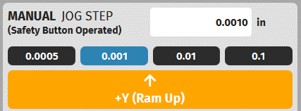
Remove the length standard from the table. Jog to machine back to the starting position by following the directions in step 7 above. Move the length standard to the right side of the table, and repeat the steps in Step 7 above.
Now that we have measurements for both sides, we can add back our length standard to get our Ram to Table opening. For this example, we obtained a position of 2.392” on the left, and 2.388” on the right. Next, we add back our length standard to both values to obtain Left and Right side Ram-to-Table opening values of 8.392” and 8.388” respectively. We note that the ram is level to within the 0.0075” threshold. Next, we average these two numbers, and enter this value into the Ram-to-Table opening setting on the Settings Menu. Click the SAVE icon to complete the process. Note: The Ram-to-Table Opening Distance is saved in the storage memory of the Titan controller PCB board. This allows the value to survive any software updates that might happen in the future without changing this value.
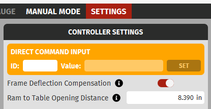


XIV. Programming a Part
1. Introduction
BendControl simplifies the process of creating bending operations on the Titan 25T press brake through an intuitive, conversational approach. The process begins with defining the essential components for a bend: Punches, Dies, and Materials. Each component is created by filling in relevant details such as punch height, die height, V-die opening, material tensile strength, and material springback.
Once the basic components are defined, these elements are utilized to create specific bend operations. For each bend, you will specify detailed parameters such as the Desired Bend Angle, Material Thickness, Punch-to-Material Clearance, and any necessary Angle Compensation.
After creating a bend operation, you can load it, along with any additional bends, into the RUN tab. This tab is designed for executing the bends on the machine through various operating modes, while providing real-time updates and controls to ensure precise and efficient bending operations. BendControl’s user-friendly interface and logical workflow make it easy to manage and execute complex bending sequences with confidence.
2. Creating a Punch
The first step in the Bend creation process is measuring and creating your Punch in BendControl. Punches come in all different shapes and sizes, including but not limited to Acute, Standard, Gooseneck, and Extreme Gooseneck. While this guide covers important considerations for punch and die selection, it does not encompass all factors necessary for determining the best tooling setup for your specific bend. Many variables influence this decision, so it is recommended to consult with a punch/die manufacturer for expert advice tailored to your specific bending needs.

A. Measuring Punch Height
Once your punch has been selected for a given bend, the first step is to create the Punch entity in BendControl by giving it a descriptive name. Next, we need to grab Calipers or a Micrometer and measure the Punch Height. Note: It’s important that this measurement is taken accurately as any inaccuracies in this measurement can cause inaccurate results when bending. If you purchased your Punch from a reputable manufacturer, it’s also possible to obtain this punch height directly from the supplier.
Punch Height refers to the vertical dimension of the punch from its tip to its shoulders (see image below). This parameter is crucial for ensuring accurate bending operations, making it essential that each punch is precisely measured for its height. Accurate measurement of Punch Height is vital for achieving consistent and precise bends.
After all information is entered, be sure to SAVE the Punch for later use.

B. Langmuir Systems Pre-loaded Punch Library
In the PUNCH drop-down menu, you may notice that some items are already populated in the software by default. These are the list of Punches that are manufactured and sold by Langmuir Systems for use with the Titan 25T machine. The Punch Height values listed here are nominal; it is highly recommended that you use measurement tools such as calipers or micrometers to accurately measure your Punches and edit any values so that they match what you have on hand.

3. Creating a Die
The second step in the bend creation process is measuring and defining your die in BendControl. Dies come in various shapes and sizes, including V-dies, U-dies, and specialty dies. By far the most common and useful die when bending on a CNC Press Brake is the 4-way Die. This Die features 4 different Die Widths that can be used by simply rotating the Die to a desired bend width.
While this guide covers important considerations for die selection, it does not encompass all factors necessary for determining the best tooling setup for your specific bend. Many variables influence this decision, so it is recommended to consult with a die manufacturer for expert advice tailored to your specific bending needs.
Note: BendControl was designed for standard Air Bending using dies with small corner radiuses. If you are using a Die with large corner radiuses, such as a Double Round Bar Die, you will need to empirically determine your desired Bend Depth, and then manually enter this value in the Bend Creation tab (see later sections).

A. “The 8x Rule”:
When selecting a die, a common guideline to follow is the 8x rule. This rule states that the minimum V-die opening should be approximately eight times the thickness of the material being bent. For example, if you are bending a material with a thickness of 1/8 inch, the V-die opening should be at least 1 inch. This rule helps ensure proper bending without damaging the material or the tooling and aids in achieving a consistent bend radius. The 8x rule provides a good starting point for die selection, but other factors such as material type and bend angle may also need to be considered for optimal results.
B. Die Height:
Once your die has been selected for a given bend, the first step is to create the Die entity in BendControl by giving it a descriptive name. Next, we need to grab Calipers or a Micrometer and measure the Die Height. Note: It’s important that this measurement is taken accurately as any inaccuracies in this measurement can cause inaccurate results when bending. If you purchased your Die from a reputable manufacturer, it’s also possible to obtain this punch height directly from the supplier.
Die Height is the vertical measurement from the bottom of the die (the surface that rests on the table) to the top surface where the material rests (see image below). This parameter is crucial for ensuring accurate bending operations, making it essential that each die is precisely measured for its height. Accurate Die Height measurement ensures consistency and precision in the bending process.

C. V-Die Opening:
The next step is to either obtain or measure the V-die opening of your die. Since many die’s have a radiused corner where the angled die surface meets the top of the die, it’s best to consult the Die manufacturer for the exact V-die opening to use, as the opening is placed somewhere along this radius.
V-Die Opening is the width of the gap at the top of the V-shaped die. This parameter is critical in determining the formed bend radius of the bend, the amount of force required, and the material thickness that can be effectively bent. Proper selection of the V-die opening ensures accurate bends and prevents material damage. A general rule of thumb is that the minimum V-die opening should be approximately 8 times the material thickness. For example, if you are bending 1/8" material, the smallest die that you should use would have a V-die opening of approximately 1".

After all information is entered, be sure to SAVE the Punch for later use.
D. Langmuir Systems Pre-loaded Die Library:
In the DIE drop-down menu, you may notice that some items are already populated in the software by default. These are the list of Dies that are manufactured and sold by Langmuir Systems for use with the Titan 25T machine. Note: the Die Height values listed here are nominal; it is highly recommended that you use measurement tools such as calipers or micrometers to accurately measure your Dies and edit any values so that they match what you have on hand.
You will also notice that the 4-way die values are listed twice; this is so that a user can select this entity if they are using our optional 4-Way Die Holder which adds an additional thickness to the Die Height.

4. Creating a Material:
The next step in the process is to create the Material that you will be bending. In many cases, it will be simplest to start with one of the pre-populated metal entities that are already in BendControl, and then duplicate and edit the values to suit your specific needs. The pre-populated materials include Cold Rolled Steel (e.g. A1008), Hot Rolled Steel (e.g. A36), Stainless Steel (e.g. 304), and Soft Aluminum (e.g. 3003 H14). The below list is the required properties that need to be defined when creating a new Material.

A. Material Tensile Strength:
The Material Tensile Strength is the maximum stress (in PSI) that a material can withstand while being pulled in tension before breaking. It's best to obtain the Mill Test Report for the material you plan to bend to get the most accurate results. If you do not have this information available, start by using the lower end of the range that can be found for your specific alloy, and compensate the Bends accordingly.
B. Inside Bend Radius Percentage:
In air bending, the inside radius that forms is expressed as a percentage of the die opening and material alloy. Sometimes this is referred to as the "20% rule". Below is a general rule of thumb for common alloy types, but please consult the relevant standards for exact values.
Cold Rolled Steel (e.g. A1008): 15-17%
Hot Rolled Steel (e.g. A36): 14-16%
Stainless Steel (e.g. 304): 20-22%
Soft Aluminum (e.g. H-series): 13-15%
C. Material Springback:
Material springback refers to the elastic recovery of metal after it has been bent on a press brake, causing the metal to partially return to its original shape. This can result in a part that appears underbent. To compensate, we can assign a fixed springback value in degrees for a given material type. While the exact amount of springback will depend on several variables, the springback value can be approximated for certain material types. Below is a generalized list of springback rates when the relationship between material thickness and inside radius is close to 1:1.
Cold Rolled Steel (e.g. A1008): 0.75 - 1 degree
Hot Rolled Steel (e.g. A36): 0.5 - 1 degree
Stainless Steel (e.g. 304): 2 - 3 degrees
Soft Aluminum (e.g. H-Series): 1.5 - 2 degrees
Copper and Brass: 0 - 0.5 degrees"
5. Creating a Bend:
The next step in our process is to create each bend for our part. Here we specify all the relevant data that defines our bend such as the Punch/Die/Materials that we are going to use, as well as our Desired Bend Angle and our Material Thickness. Since we are also going to use the backgauge to position the material for our bend line, we can specify this information here as well. The following sections provide more detailed information for each parameter on the Create Bend screen.

A. Selecting Punch/Die/Material:
The first step to creating our bend is to select the Punch/Die/Material combo that we want to use for our bend. Simply select the desired item from each drop-down menu as shown below. These selections can be changed at any time, and any changes to these entities on the Punch/Die & Materials tab will propagate back to the Create Bend tab as well.

B. Desired Bend Angle (Included):

Next, we enter our Desired Bend Angle in degrees. The Desired Bend Angle is the inside angle formed in the material during the bending process, also referred to as the included angle. The below image provides several examples for how an included angle is specified. It’s important to enter your angle correctly using this method to ensure the desired bend angle is produced.

C. Material Thickness:
This value is the thickness of your material in inches. It is very important to get an accurate measurement of your material thickness, because inaccurate values can lead to large inaccuracies in finished bend angles. We highly recommend using a caliper or micrometer to measure your material thickness when creating a bend. An accurate material thickness measurement becomes even more important when you are bending thin material on a die with a narrow V-die opening.
D. Angle Compensation:

Angle Compensation allows the operator to make an angular correction to a programmed Bend. The user can make a bend, measure the difference when compared to the desired bend angle, then enter this correction value allowing the machine to compensate for the error on the next bend. Angles that are OVERBENT are bent past their desired angle (e.g. desired 90° but bent to 85° is 5° OVERBENT). Angles that are UNDERBENT are not bent enough when compared to their desired angle (e.g. desired 90° but bent to 95° is 5° UNDERBENT). Clicking the OVERBENT/UNDERBENT button will toggle between these two settings.

E. Bend Width:
Bend Width is a measurement of the width of the workpiece across the table. The wider the workpiece is, the more tonnage is required to make the bend. BendControl uses the bending parameters for each bend to make a calculated estimate of the needed Tonnage for each bend, so it’s important that you accurately measure your bend width to get a more accurate Calculated Bend Tonnage value in BendControl for each bend.

F. Punch-to-Material Clearance (Start):
Punch-to-Material Clearance is the vertical distance between the Safety Jog Plane and the top surface of the material before clamping or making a bend. This distance must be large enough to freely adjust the workpiece between the Punch and Die, but small enough to ensure a finger could not fit between the Punch and the material for safety reasons. BendControl will issue a Warning if the Punch-to-Material Clearance value is greater than 0.3 inches.

G. Additional Retract After Bend:
Additional Retract After Bend allows the ram to retract upwards past the original Safety Jog Plane (a.k.a the Punch-to-Material Clearance Position) once a bend is completed. This adds additional retraction enabling the user to remove their workpiece after a bend is complete, if necessary depending on the finished part geometry. The below image depicts a part geometry that would require this additional clearance distance in order to properly remove the material from the front of the machine.

H. Setting up a BACKGAUGE move (Optional):

An optional step when creating a Bend is adding a backgauge move. This requires the operator to have purchased the optional 2-axis CNC backgauge. A backgauge is designed to accurately position a workpiece in place for bending, ensuring precision and consistency in the bend line position. Essentially it is the backgauge's job to automatically move its finger stops into position for each programmed bend so that the operator can use this as a 'backstop' to push the material against before bending.
To enable a backgauge move, toggle the ‘Add Backgauge Move’ to the ON position. You will see the below panel pop-up at the bottom of the Create Bend screen.

The first step to defining a Backgauge move is to specify the Reference Edge Stop that you will be using on the backgauge. Generally this will be either the Finger Lower Edge, or the Finger Upper Edge, but it’s possible that you have replaced your fingers with some other custom feature (such as an angled finger for locating an angled part feature) and this can be selected here if this Reference was defined on the backgauge Tab of BendControl. See OPERATING THE BACKGAUGE section below for more information on how to define reference edges on the backgauge Tab.
Next, you will specify the X and the R backgauge coordinate positions for your required bend. This tells the backgauge where to move before the bend process occurs so that the operator can snub the material up to the Reference edge hard stop for making the required bend. A user can also specify the Jog Speed that they want the backgauge to move during a program.
As a simple example, let’s say that we wanted to create a 2” Flange in ⅛” steel. From our CAD model, we see that given the inside bend radius (which can be taken from the Create Tab in BendControl and substituted into the CAD model for more accurate positioning), the Bend Line Location is 1.967” from the edge of our material. If you don’t have access to 3D modeling software to extract the Bend Line Location, we recommend consulting an online reference or calculator for how to calculate the Bend Deduction for your specific bend in order to position the Bend Line Location for your desired Flange dimensions.
Let’s assume that we are using the backgauge finger Upper Edge as our reference edge to snub the material against. Let’s also assume that we zeroed the Upper Edge stop to the Centerline of our machine in the X Position, and we zeroed the R position so that the finger surface was flush to our top Die surface where the material rests (see pictures of this setup on the Machine below as an example). Then, we would program the backgauge move as shown in the image below. We have also typed in Backguage Zero Origin Notes to save with our bend and remind us next time we run this program how to zero the backgauge finger stops before starting the bend again.

a. Setting our X-axis ZERO Position on the Machine:
In the previous example, we have shown how to enter in this backgauge position for creating a Bend. Now let’s look at how we actually establish these Zero positions for our desired reference edges on the machine itself. Note: You must HOME your backgauge before continuing here (see later section OPERATING THE BACKGAUGE for more information on how to run the backgauge and Home it).
As we saw earlier, we are going to use the Upper Finger Edge for this bend. In addition, we want the Zero position of our X-axis to be located at the Centerline of the machine table. Unfortunately, the backgauge fingers are not able to jog to the Upper Finger Edge all the way to centerline, but we can jog the Lower Finger Edge to the centerline. Since we know that the Upper Edge is exactly 1.000in set back from the Lower Edge in the positive X-axis direction, we can enter this offset when we Zero the X axis.

Now with the Lower Fingers sitting at the Machine Centerline, let’s navigate to the Backgauge tab to set our X-axis zero position. Since we know that the Upper Finger edge is set back in the positive X direction by exactly 1.000”, we can just type in 1.000” into the Digital Read Out (DRO) for the X-axis and we are done. If we had enough clearance and could jog the Upper Edge so that it was in-line with the Machine Centerline, we would find that the position for the X-axis would read 0.000”, just like we want it to. It will look something like below in BendControl when you are finished. Remember to make sure that you have selected BACKGAUGE FINGER UPPER EDGE from the drop-down menu above the Digital Read Out for X and R-axis positions.

b. Setting our R-axis ZERO Position on the Machine:
Next, we are going to do the same thing but this time for the R-axis zero position. To do this, we just need to jog the R-axis until the material resting surface is flush to the top surface of the Die, and then we can just click the ZERO button next to the R-axis DRO position in BendControl. When done correctly, it will look like the image below.


c. Demonstrating Backgauge Positioning During Bending Process:
Now that we have our X and R-axis Zero positions set correctly, and we’ve entered our backgauge bend line coordinate positions into the Create Bend screen for our desired bend, we can take a look at where the machine will move automatically when we actually run the bend process. As shown below, the backgauge is now positioned so that the material can be loaded, snubbed up to the hard stop of the backgauge Upper Reference Edge, and bent to our desired 2” flange. This same procedure can be followed for zeroing and entering backgauge coordinates for any desired bend.

I. Override Final Bend Position (Optional):
BendControl allows the user to override the Final Bend Position, as long as it is between the clamp position and the maximum machine travel distance. Sometimes this can be useful if the calculated values are not producing the desired bend, and you want to use a bend depth value that you have empirically determined works well for the bend that you are making.
PROCEED WITH CAUTION ON ANY OVERRIDDEN BEND TO MAKE SURE THAT YOU DON'T CRASH YOUR PUNCH INTO THE DIE.
We have found that the best way to determine an Overridden Final Bend Position is to run some test pieces using Manual Mode. This will allow you to incrementally creep up on your desired Bend, and then you can use this empirically determined value to create the Bend for running in a program once you have it dialed in. Below is an example of a Bend that has been overridden.

J. Calculated Bend Tonnage:

Calculated Bend Tonnage is the calculated total tonnage required to perform a bend, and it is displayed on the right side of the Create Bend tab. If the Calculated Bend Tonnage is greater than 12.5 tons (the maximum allowable tonnage for each hydraulic cylinder), then the workpiece must be centered to distribute the load between the rams evenly.
K. Predicted Inside Bend Radius:
The Predicted Inside Bend Radius is an estimated calculation of the inner radius formed by a bend, based on the relevant parameters entered into BendControl. This value is particularly useful as it can be directly applied to a part's CAD model, ensuring a more accurate determination of the bend line within the CAD design.


L. Bend Warning Labels:
When creating bends on the Create Bend tab, BendControl will perform checks of the entered parameters to make sure that there are no issues with the bend. BendControl employs two different warning labels to alert operators to potential issues with their bends, ensuring both safety and precision during operations. These warnings are displayed in the Create Bend Tab and are categorized by color to indicate their severity and impact on the bending process.
Yellow Warning Labels: These labels, such as "Unsafe Clearance Plane" and "Overridden Bend Depth," alert the operator to specific issues that require attention but do not prevent the bend from being executed. The yellow warnings serve as advisories, allowing the bend to proceed while highlighting potential risks or deviations from standard parameters. Operators should carefully review these warnings and take appropriate actions to mitigate any identified risks.
Red Warning Labels: These labels, such as "Tonnage Rating Exceeded" and "Upper Travel Limit Exceeded," indicate critical issues that prevent the bend from being executed on the machine. Red warnings highlight problems that pose significant risks to the machine or the bending process, necessitating immediate resolution before the operation can continue. These labels ensure that operations are halted to avoid damage or unsafe conditions, protecting both the equipment and the operator.
By paying close attention to these warning labels, operators can ensure safe and efficient bending operations, addressing potential issues proactively and maintaining the integrity of the bending process. Below is an example of the warning labels issued for a given Bend.

M. Reviewing Bend Positions and Saving:

In the Create Bend tab of BendControl, operators can review the calculated positional information for each bend on the right hand side. This includes several critical parameters displayed in a clear, accessible format:
Start Safety Clearance Position (Machine Coordinate): This is the vertical position where the ram will stop before clamping the material, ensuring enough clearance for positioning the workpiece.
Bend Clamp Position (Machine Coordinate): The position where the ram will clamp the material securely before initiating the bend.
Final Bend Position (Machine Coordinate): The target depth the ram will achieve to form the bend.
Retract After Bend Position (Machine Coordinate): The position to which the ram will retract after the bend is completed, allowing safe removal of the workpiece, and convenient positioning to start the next bend.
Total Bend Stroke: The total vertical movement of the ram during the bending process.
Once all parameters are confirmed, remember to click the  icon to continue.
6. Creating a Bend Program:
The RUN tab is the central hub for creating, managing, and executing bend programs in BendControl. This interface allows operators to create and add new bends to a program, review detailed information for each bend, edit or delete bends, and save the program for future use. The intuitive design ensures that all necessary information and controls are easily accessible, facilitating efficient and precise bending operations.
A. Adding a Bend to a New Program:
First click the  button to create a new Bend program. Next, to add a bend to a new program, click the
 button located at the bottom right of the screen. This will open the Add Bend Move window, where you can select
any of your created bends from the Create Bend tab.Simply select the Bend you want from the list, and click Add Bend to add it to your program.
button located at the bottom right of the screen. This will open the Add Bend Move window, where you can select
any of your created bends from the Create Bend tab.Simply select the Bend you want from the list, and click Add Bend to add it to your program.

B. Rearrange Bends in a Program:
In the RUN tab, operators can quickly change the order of bends within a program using the touch screen interface. To rearrange a bend, touch and hold the six-dot symbol (also known as the handle icon) next to the desired bend, drag it to the new position, and release it. This action updates the program sequence instantly (don’t forget to SAVE), allowing for quick adjustments to the bending process on the fly. Below is an example of a Bend that is in the process of being rearranged.

C. Bend Information Display:
The program display allows a user to verify information for each loaded bend. This is a handy reference to make sure that all of your bends and bend information looks correct before proceeding. Some of this information includes Start Position, Clamp Position, Punch, Die, Material, Thickness, Desired Bend Angle, Angle compensation, Backgauge move information, and expected Bend Tonnage.
D. Editing or Deleting a Loaded Bend:
To delete or edit a bend, use the icons next to each bend entry:
Delete Bend: Click the red trash icon to remove the bend from the program. This action will prompt a confirmation to ensure that the bend is not deleted accidentally.
Edit Bend: Click the blue pencil icon to open the selected bend in the Create Bend tab. This allows for quick modifications to the bend without having to recreate the bend from scratch. Any changes saved here will propagate to the program automatically.
E. Reviewing and Saving:
After configuring all the bends in the program, it is crucial to review the entire sequence to ensure accuracy and safety. Verify that each bend has the correct parameters and that the sequence order is appropriate. Once satisfied, click the "SAVE" button at the top right of the screen to store the program.
XV. Running a Bend Program:
Now that we have created our Bend program, it’s time to actually run it on the Titan 25T machine. This will involve interacting with the machine and its peripherals in order to create our desired part. Before running a program, it's important to understand the entire process to make sure that everything runs smoothly. Once you become more familiar with the machine and the bending process, the operator can focus on how to optimize programs for making quicker and more efficient bends.
1. EMERGENCY STOP Switch:
The EMERGENCY STOP switch is a critical safety feature located at the top right of the machine, next to the touch screen. Operators should always be aware of its location and keep a mental eye on it while running programs. In case of an unexpected event, pressing the EMERGENCY STOP switch will immediately kill all power to the entire machine, ensuring a swift and safe shutdown.
2. KILL HYDRAULIC POWER Button:

The KILL HYDRAULIC POWER button is another essential safety feature, located in the bottom right corner of the BendControl software interface. Clicking this button at any time will stop the hydraulic power pack from running, providing an additional layer of safety if something unexpected happens while running a program. This feature allows operators to quickly halt hydraulic operations without affecting the rest of the machine's functions.
3. CANCEL (or STOP) Button:

The 'Cancel' button, located at the bottom right corner of BendControl, serves multiple purposes. When a program is paused at a HOLD state, clicking the 'Cancel' button will cancel the program. This is a soft reset, and the operator can continue to start the program again without needing to Home the machine again. During active motion, this button changes to 'Stop.' Pressing it while the machine is moving will stop all motion and cancel the program instantly, providing an immediate response to halt operations if necessary.
4. Bending Modes
At the bottom right of the RUN tab, the user will find the Bend Mode Drop-down menu. This allows a user to select a desired Mode for a given bend or program (multiple bends). Below is a description of each mode and how it operates when running the program.

A. SINGLE BEND MODE:
In Single Bend Mode, the BendControl software executes the selected bend operation once and then finishes the program. This mode is available when the active program contains only one bend or when a specific bend is highlighted in a multi-bend program. It is ideal for verifying individual bends before proceeding with additional operations.
B. SINGLE BEND REPEAT:
Single Bend Repeat mode allows the operator to continuously repeat the selected bend operation after it has been successfully completed. This mode is also available when the active program contains only one bend or when a specific bend is highlighted in a multi-bend program. The operator is provided with a clear warning in the RUN PROGRAM pop-up indicating that the bend will be repeated, ensuring they are aware of the continuous operation.
C. PROGRAM BEND MODE:
Program Bend Mode enables the execution of a sequence of bends starting from the currently highlighted bend and proceeding to the last bend in the active program. This mode is accessible when the active program has more than one bend. If the selected bend is not the first bend in the program, the RUN PROGRAM pop-up includes a warning to inform the operator that the sequence will start from the highlighted bend and not from the beginning.
D. PROGRAM BEND LOOP:
In Program Bend Loop mode, the BendControl software runs the entire sequence of bends from the first to the last bend in the program, regardless of the currently selected bend, and then repeats the sequence continuously. This mode is suitable for high-volume production runs requiring repeated application of the same sequence of bends. The RUN PROGRAM pop-up provides a warning to clearly inform the operator that the program will repeat, ensuring awareness of the continuous operation.
5. Actively Selecting a Bend:

In BendControl, actively selecting a bend is crucial for utilizing the various Bend Modes effectively, and to ensure that your machine runs how you expect it to when starting a program. To select a bend, simply tap on the desired bend in the program list on the RUN tab. The selected bend will be highlighted by a Red bounding box, indicating it is the active bend. This selection determines the starting point for the operation modes as below:
Single Bend Mode: Executes the currently highlighted bend once and then finishes.
Single Bend Repeat: Repeats the actively selected bend continuously after each successful completion, with a clear warning in the RUN PROGRAM pop-up at the start.
Program Bend Mode: Begins the sequence from the actively selected bend and proceeds to the last bend in the program. If the selected bend is not the first in the program, a warning will be displayed in the RUN PROGRAM pop-up to inform the operator.
Program Bend Loop: Starts from the first bend in the program, regardless of which bend is currently selected, and repeats the entire sequence continuously, with a warning in the RUN PROGRAM pop-up indicating the looped execution.
By actively selecting a bend, operators can control the starting point and behavior of the bending process, ensuring flexibility and precision in their operations.
6. Sequence of Bending Operations:

When the operator clicks the RUN button to start a bend program, a linear progress bar appears in BendControl at the bottom of the screen which illustrates the chronological sequence of steps that the machine will follow. This progress bar provides real-time feedback, showing which step the machine is currently executing and advancing to as each step is completed. The Sequence of Bending Operations is designed to ensure a precise and efficient bending process, from initial positioning to the final bend and retraction. Below is a detailed description of each step in the sequence.
A. Step 1 - Backgauge Move (optional):
In this optional step, the backgauge moves to the predefined position to correctly position the material for the bend. This ensures that the material is accurately aligned with the punch and die setup. The backgauge settings, including the X and R coordinates, are specified in the program to match the desired bend line location.
B. Step 2 - Safety Start Position:
This step moves the ram down the Safety Start Position, so that we can feed our material between the Punch and Die to start the bending process. The ram is moved during this step using the Safety Palm Switches.
C. Step 3 - Clamp Material:
In this step, the ram moves down further to clamp the material securely between the punch and die. Clamping the material ensures that it remains in the correct position to start the bending process, and the operator can then remove their hands from holding the material to safely make the bend. The ram is moved during this step using the Foot Pedal Switch.
D. Step 4 - Backgauge Bump (optional):
The Backgauge Bump is an optional step that involves a slight movement of the backgauge backwards (+X direction) after the material is clamped. This helps to clear the backgauge fingers from the material before the bending process is started.
E. Step 5 - Bend Move:
The Bend Move is the core step where the actual bending operation occurs. The ram continues to move downwards, applying force to bend the material to the specified angle between the Punch and Die. The ram is moved during this step using the Foot Pedal Switch. Note: If the AUTO CLAMP-to-BEND toggle is ON (see more information in section below), the foot pedal can remain down from the Clamp Material step in order to continue making the Bend move.
F. Step 6 - Backgauge (optional) & Ram Retract:
In the final step, the ram retracts automatically to the Retract After Bend Position, ensuring safe clearance for the removal of the bent workpiece. If a backgauge move was involved, the backgauge will simultaneously retract backwards in the +X direction by a predefined amount (set in the Settings tab).
7. Operating Safety Palm Switches:

The Safety Palm Switches are an essential safety feature of the Titan 25T CNC Press Brake, designed to ensure that the operator's hands are clear of the machine during critical movements. These switches must be actuated simultaneously to bring the ram down to the Safety Clearance Plane before executing a bend. This dual-hand operation prevents the operator's hands or arms from being in the machine's danger zone during movement.
Whenever the machine is armed with a safety jog move and is in the SAFETY JOG HOLD state, the Safety Palm Switches need to be engaged to initiate the move. The operator can release and re-engage the switches as needed to incrementally move the ram, allowing for periodic checks of the machine's status and position. This incremental control is particularly useful for precise adjustments and ensuring that the setup is correct before proceeding with the bend.
To prevent misuse, the Safety Palm Switches cannot be bypassed with tape or other means. BendControl includes a safety mechanism that verifies the switches are released before a safety jog move can be armed. This ensures that the palm switches are operated correctly, maintaining a high level of safety during machine operation.
By adhering to these safety procedures, operators can confidently perform bending operations while minimizing the risk of injury.
8. Operating the Foot Pedal:

The Foot Pedal on the Titan 25T CNC Press Brake is used to perform the clamping and bending strokes. To enhance safety and prevent accidental activation, the foot pedal must be "double-tapped" to start a move. This means the pedal should be quickly depressed and released, then depressed again and held down to complete the clamp or bend stroke. This mechanism ensures that the operator is intentionally engaging the pedal to execute a move, and doesn't inadvertently step on it by accident.
Once a clamp or bend move is armed, the operator can use the foot pedal to initiate the action. For added safety, the foot pedal must be released before a new clamp or bend move can be armed. If the foot pedal is released at any time during a clamp or bend move, the program is immediately canceled, and the ram automatically retracts to the Safety Clearance Plane. This feature acts as an additional safety measure, instantly stopping the program if the operator releases the pedal.
Additionally, there is an optional feature called AUTO CLAMP-to-BEND that can be toggled on. When this feature is enabled, the operator can keep the pedal depressed between the clamping and bending moves, allowing for a seamless transition during the bending operation. This streamlines the process and improves efficiency while maintaining safety protocols.
By following these procedures, operators can ensure safe and efficient operation of the foot pedal, minimizing the risk of accidental activation and maintaining control over the bending process.
9. AUTO CLAMP-to-BEND Toggle:

At the bottom of the RUN tab is a toggle button labeled AUTO CLAMP-to-BEND. When this toggle is ON, the AUTO CLAMP-to-BEND feature is enabled when running a program, and the Dwell time is also listed in the button for easy reference. When this feature is enabled, the operator is able to leave the Foot Pedal depressed after a CLAMP move has been completed, and the machine will automatically start the BEND move after the dwell period has been completed.
For those that are new to operating the machine, this Dwell feature is a great added safety step to give the operator time to make sure everything went according to plan during the Clamp phase, and before the Bend operation begins. If the operator lifts the foot pedal during this dwell period, the ram will retract back to the Safety Start Position and the program will be canceled. Below is the pop-up that is shown to a user during the dwell period when the timer is counting down. If you want the AUTO CLAMP-to-BEND feature enabled, but don’t want any dwell period, you can simply set this value to 0 seconds in the settings menu.

10. Monitoring the Live Report Menu While Bending:
The Live Report Menu within BendControl provides real-time data and control options essential for monitoring and operating the Titan 25T CNC Press Brake. This panel is divided into several key sections described below. It is highly recommended to familiarize yourself with all the data that is contained in this reporting menu so that you are in a position to make better decisions while operating the machine.

A. Machine Status: This indicates the live state of the machine controller at any given time.
B. Current Position: Displays the current commanded position of the ram in inches.
C. Home Position: Indicates the default home position, if the current position is at the home position of -0.050in.
D. Y1 and Y2 Positions: Shows the individual live positions of the Y1 and Y2 hydraulic cylinders, expressed as the live readout from the linear glass scales encoders on each side of the ram.
E. Y1/Y2 Delta: Displays the live positional difference between Y1 and Y2 cylinders.
F. Y1 and Y2 RAM Load: Shows the live load in Tons on each Ram. As tonnage increases, the bars will increase in height accordingly, up to a maximum of 12.5 tons for each ram.
G. Total Load: Indicates the combined load being applied by summing up the live Y1 and Y2 loads.
H. Live Ram Velocity: Shows the actual live speed of the ram movement in inches per minute (IPM).
I. Safety Jog Buttons LEDs: Shows the live state of the Safety Jog Button Palm Switches for the left and right sides. When these buttons are depressed, the lights will turn green.
J. Foot Pedal LED: Shows the live state of the foot pedal. When the foot pedal is depressed, the light will turn green.
K. Anti-Bind Switch: Shows the live state of the Anti-Bind Switch. When either of the Anti-Bind limit switches are tripped, the status light will turn green.
L. Commanded Jog: Shows the currently commanded Jog Position and Jog Speed of the machine in inches.
M. Distance to Go: This signifies the linear distance that the ram has to travel from its current position in order to complete the commanded jog move. It is a very useful feature to monitor during bending operations as a sanity check to make sure that the ram is going to move where you expect it to move.
11. Measuring and ‘Comping’ a Bend:

The last step when making a part on the machine is to measure and compensate for the bend angle, if needed. Generally the operator will first execute a bend, and then use a protractor to measure the actual angle that was made. Then, the operator can figure out the difference between the measured angle and the desired angle to arrive at the compensation that is needed (either OVERBENT or UNDERBENT). Angles that are OVERBENT are bent past their desired angle (e.g. desired 90° but bent to 85° is 5° OVERBENT). Angles that are UNDERBENT are not bent enough when compared to their desired angle (e.g. desired 90° but bent to 95° is 5° UNDERBENT). Clicking the OVERBENT/UNDERBENT button will toggle between these two settings.
The example part below was bent on Titan to 90.6 degrees. This indicates that it was UNDERBENT by 0.6 degrees, since our Desired Bend Angle was 90 degrees. We simply type 0.6 and toggle the Angle Compensation to UNDERBENT, and we can make the bend again.


NOTE: If you are making several parts in a row, comping the bend is a worthwhile process. But if you are just making a one-off part and the part is overbent, there is no way to bend it back. That is why it’s advisable to enter a larger angle then what you need, then you can iteratively creep up on the desired angle by rebending and checking again. For example, if you wanted a 90 degree bend, you might try to input an OVERBENT value of 2 degrees. Then you can measure and check the bend, and adjust the compensation as needed.
XVI. Manual Mode Operation
Manual Mode is a special menu that can be accessed by clicking the MANUAL MODE tab. Due to the increased risk for injury in Manual Mode, the user will be greeted with a Safety disclosure each time that Manual Mode is entered.
Manual Mode is a great way to operate the machine like a regular hydraulic press, but with all the numerically controlled features of a CNC machine. Manual Mode features three different operating modes which include MANUAL STROKE OPERATION, MANUAL JOG STEP, MANUAL CONTINUOUS JOG, and MOVE TO POSITION. In addition, when in Manual Mode, the user can temporarily decrease the Max Tonnage Per Ram setting to a lesser value than the maximum 12.5 Tons. This can be important when a user might want to limit the max tonnage of the machine, such as when pressing a bearing into a bore, or other assembly and bending tasks where it is important to control the maximum load. The below sections go into greater detail on how to operate each of these Modes.
1. Extreme Caution in Manual Mode:
Please exercise Extreme Caution when operating in Manual Mode. Several of the parametric safety checks that are present in normal program bending operations are not present in Manual Mode, the risk of injury due to incorrect operation is much greater.
Responsibility: You assume full responsibility for ensuring all operations conducted in Manual Mode comply with the established operating guidelines and safety protocols.
Parameter Verification: It is imperative that you double-check all parameters you input manually to confirm they are correct and suitable for the intended operation. Incorrect parameters can lead to machine malfunction, damage, or failure, posing serious risks.
Safety First: Always prioritize personal and workplace safety. Ensure you are fully versed in emergency stop procedures and safety equipment usage before initiating Manual Mode.
Training and Competence: You confirm that you are adequately trained and competent in operating the CNC Press Brake, particularly in Manual Mode, and understand the risks involved.
Injury Risk: Be aware that incorrect usage of Manual Mode can lead to serious injury. Always follow best practices and never bypass safety features.
2. Set Temporary Tonnage Limit:

The "Set Temporary Tonnage Limit" feature allows operators to temporarily reduce the maximum Ram tonnage capacity of the Titan 25T when in Manual Mode. By decreasing this value, the machine will enter into the Maximum Tonnage Error state at this new setting value. This is particularly useful for delicate tasks that require lower force to, such as pressing bearings into bores or working with thin materials during assembly tasks. By setting a lower tonnage limit, operators can prevent overloading and potential damage to the workpiece or machine, ensuring precise and safe operation.
3. Manual Stroke Operation:

The Manual Stroke Operation provides direct control over the Ram's movement, allowing operators to manually set the start and end positions of the ram stroke to create a mini-program to run. This feature can be very useful if you want to bend parts on the machine manually, by specifying a starting and end point in Machine coordinates. Once a start and end point has been entered, the program will calculate the total stroke distance and display this value as well. In addition, a Safety Plane Clearance value can also be added, which places additional clearance above the start position in order to have room to load material before the stroke operation begins.The feature also has a ‘Repeat’ toggle which will allow the program to run continuously on repeat until the user cancels it. This can be very valuable if you need to make several copies of the same part, or if you are performing the same assembly task over and over again with the press. The Safety Plane move is operated by the Safety Palm Switches, and the manual stroke operation is Foot Pedal Operated.
Another great use for this Manual Stroke Operation is when you want to operate the machine like a regular Press, but with numeric controls built in. For example, let’s say that you want to press fit a 20mm tall bearing into a tight bore. You could set the Start Ram Position for your setup, and then set your Ending Ram Position so that it strokes the needed 20mm to press the bearing into the bore. Then you could enter a Clearance value that lets you slide the bearing into position, and then you can run the program. It can also be valuable to reduce the Max Tonnage Per Ram setting if you want to protect your parts from the full 25 Tons of the machine when doing more delicate work.
4. Manual Jog Step:

The Manual Jog Step panel in BendControl allows precise control over the ram's position by allowing it to move in small, incremental jog steps. Operators can select a jog step size from the available options (0.0005”, 0.001”, 0.01”, or 0.1”, or a custom value entry) and then use the +Y (Ram Up) and -Y (Ram Down) buttons to adjust the ram position accordingly. This feature is operated via the Safety Palm Switches to ensure safe jogging movement of the Ram. Additionally, the Repeat toggle allows continuous movement in the Down direction, facilitating efficient ram positioning during setup and adjustments.
5. Manual Continuous Jog:

Manual Continuous Jog enables the operator to move the ram down continuously so long as the Safety Jog Buttons are still depressed. This feature is useful for quickly positioning the ram to a desired location without needing to enter specific coordinates. It provides a convenient way to make larger adjustments to the ram position, facilitating efficient setup and adjustments during the bending process.
6. Manual Move To Position:

The Move To Position panel in Manual Mode allows operators to command the ram to move directly to a specified position along the Y-axis. By entering the desired Y-axis ram position (in machine coordinates), and pressing the RUN button, the ram will move precisely to the specified location once the Safety Palm Switches are operated. This feature is operated via the safety button to ensure secure handling. The Move To function is essential for setting up exact positions for bending operations, ensuring accurate and repeatable results during the bending process.
XVII. Operating the Backgauge
In this section we will review the features of the Backgauge Tab in BendControl. This section assumes that you have already assembled, squared, and Homed your backgauge successfully using the Backgauge Assembly Guide. If you have not done so already, please refer to this section of the guide before continuing.
1. Homing the Backgauge
Homing the backgauge is the first step to ensure accurate positioning during bending operations. The CNC backgauge includes automatic dual-axis squaring on both the X and R-axes. This ensures that if a crash happens on the machine, the backgauge can be simply homed to resquare itself to the machine frame.
To home the backgauge, click the "HOME" button located at the top left of the Backgauge tab. This will initiate the homing sequence,
calibrating the X and R axes to their default positions. The status indicator at the bottom right will display "IDLE" once the homing process
is complete, indicating that the backgauge is ready for use. The Homing button will also  , indicating that the machine is homed.
2. Jogging the Backgauge
Jogging the backgauge allows for precise manual adjustments to the backgauge position. This can be done using the Jog Arrow D-Pad via touchscreen input, or with an optional wireless Jog Pendant.
A. Jog Arrow D-Pad:

The Jog Arrow D-Pad is located on the left side of the Backgauge tab and provides directional control over the backgauge. Press the arrows to move the backgauge in the desired direction:
X- (left), X+ (right), R- (down), or R+ (up). This allows for fine-tuning the position of the backgauge to align with the workpiece accurately.
B. Jog Step Mode:

Jog Step Mode allows for incremental adjustments to the backgauge position. Select the desired step size (0.0005", 0.001", 0.01", 0.1", or custom input) from the Jog Step options. Use the Jog Arrow D-Pad to move the backgauge in precise increments, enabling fine control over the positioning.
C. Continuous Jog Mode:
In Continuous Jog Mode, the operator can click and hold down a directional arrow on the Jog Arrow D-Pad to move the backgauge continuously in the selected direction. The backgauge will keep moving as long as the button is held down, and it will stop immediately when the button is released. This mode is useful for making larger adjustments quickly and efficiently. If you are using the optional wireless Jog Pendant, the left/right/up/down arrows on the keyboard can be used to jog the backgauge.
3. Move To Position:

The Move To Position feature allows the operator to command the backgauge to move directly to a specified X and R coordinate. Enter the desired coordinates in the "MOVE TO" fields and click the "RUN" button. The backgauge will automatically move to the specified position, ensuring accurate and efficient setup for bending operations.
4. Reference Edge Drop-Down:

The Reference Edge Drop-Down menu, located at the top right of the Backgauge tab, allows operators to select the reference edge for the backgauge. By default, the menu includes pre-loaded options BACKGAUGE FINGER LOWER EDGE and BACKGAUGE FINGER UPPER EDGE. These options refer to the lower and upper edges of the backgauge finger, respectively.
Additionally, the drop-down menu provides the flexibility for users to customize their reference edges. Users can select any of the "SELECT TO RENAME'' options to define and rename a custom reference edge. This feature is particularly useful if the operator is using a custom-made stop on the backgauge fingers. By accurately naming these custom reference edges, operators can ensure precise positioning and repeatability for their specific bending requirements.
5. Limit Switch State LEDs:

The Limit Switch State LEDs provide visual indicators of the four limit switch states on the backgauge (red means triggered, gray means closed). These LEDs can be useful when trying to track down issues with limit switches or homing.
6. Example of Using the Backgauge for a Bend:
To see an example of how a backgauge position is set for a desired operation, visit the above section titled: Setting up a BACKGAUGE move (Optional).
XVIII. Settings Menu Overview

1. Material Clamp Rate:
Material Clamp Rate is a percentage of the material thickness. This is the distance the ram will stroke down to when the material is clamped during a programmed bend (e.g. a 1/8" thick material with a 10% Material Clamp Rate would cause the ram to stroke down 0.012" to clamp the workpiece between the Punch and Die before the bend stroke starts).
2. Automatic Clamp-to-Bend Dwell
Automatic Clamp-to-Bend Dwell refers to the time interval between the end of clamping and the start of a bend during a programmed bend cycle when the Auto-Clamp-to-Bend feature is enabled. Once the material is clamped, the user simply keeps the pedal pressed, and the program will automatically proceed to the bend stroke after the dwell period has elapsed. If the user releases the pedal during the dwell period, the program is canceled, and the ram will retract to the Safety Plane.
3. Backgauge Retract Between Bends:
Backgauge Retract Between Bends is an optional parameter that enhances part clearance. After a bend is completed and the ram begins retracting to the Safety Retract Plane, the backgauge simultaneously retracts towards the back of the machine. This movement provides additional space for removing the part before starting the next bend sequence.
4. Backgauge Bump Off Distance:
Backgauge Bump Off Distance is an optional parameter that ensures precise part positioning before a bend sequence. After the part is clamped, the backgauge moves back in the X direction by the specified distance just before the bend sequence begins. This movement helps to prevent any potential interference between the backgauge and the part, ensuring a smooth and accurate bending process.
5. Frame Deflection Compensation:
Frame Deflection Compensation is a parameter designed to ensure precision in the bending process by accounting for frame deflection. By monitoring the tonnage on the Y1 and Y2 rams, the system calculates and compensates for any lost motion due to frame deflection. This is achieved by stroking an additional distance, ensuring the bend is accurate and consistent despite the deflection of the machine's frame.
6. Ram to Table Opening Distance:
Ram to Table Opening Distance is the measurement from the bottom surface of the ram to the top surface of the table. This parameter is crucial for defining all strokes on the machine. Accurate measurement of this distance is essential, as any discrepancies can lead to inaccurate bends.

7. Update Machine/Backgauge FW and Software From USB Drive:
In the settings menu, we can also update our Machine/Backgauge firmware, as well as update the BendControl application. See the below section titled Flashing Firmware/Software Updates from USB Thumb Drive (if no internet access available) for more information.
XIX. Bleed Hydraulics Procedure
BendControl has a built-in Bleed Wizard for bleeding and priming the Y1 and Y2 hydraulic systems. To access the Bleed Wizard, click on the  button
located in the top right Header menu in the software.
button
located in the top right Header menu in the software.
A. Preparing to Bleed Hydraulic Cylinders:
The following procedure can be used to bleed the air out of the hydraulic system for both the Y1 and Y2 cylinders. This process allows manual operation of both hydraulic cylinders separately (by using the corresponding Safety Palm Switches), enabling the bleeder screws to be opened to circulate hydraulic fluid back into the reservoir until all air bubbles are removed.
Remove All Punches & Dies: Ensure all punches and dies are removed from the machine. The ram can still move downward under pressure during the bleeding procedure. For safety, do not place any part of the body between the ram and the table of your machine.
Remove Fairing Covers: Take off the fairing covers from the left and right hydraulic cylinders to locate the bleeder screw/hose assembly.
Obtain a Wrench: Use a 9/16" open-end wrench to perform the bleeding procedure.
Next click the  to continue.
B. Bleeding Hydraulic Cylinders
Once Priming Mode is enabled, the following steps can be used to bleed air and prime both Y1 and Y2 hydraulic systems. Follow the steps below to bleed each hydraulic ram separately until both are completed.
In order to continue, you will need to remove all punches and dies from your machine. While the movement might be slow, the ram is still capable of moving downward under pressure during the bleeding procedure. For your safety, do not place any part of the body between the ram and the table of your machine.
Procedure Steps
1. Y2 Hydraulic Ram (Right-hand Side)
- Press and hold down the right-hand palm safety switch.
- Once the right-hand servo motor is heard spinning, with the palm switch still pressed down, unscrew the bleeder screw at least 1/4 turn. Hydraulic fluid should flow through the bleeder hose and back into the tank.
- A mixture of hydraulic fluid and air bubbles should travel through the bleeder hose into the reservoir tank.
2. Tighten Bleeder Screw
- Once all air bubbles have stopped flowing, with the palm switch still pressed down, tighten the bleeder screw.
- Once tightened, release the palm switch and re-attach the right-hand fairing cover.
3. Y1 Hydraulic Ram (Left-hand Side)
- Repeat the above procedure for the left-hand hydraulic ram.
- After completion, exit the wizard and home the machine to continue normal operation.
XX. Backup & Restore Menu
The Backup & Restore menu can accessed by selecting the icon in the top right corner of the Header Menu. This allows you to create a save point that you can restore to at any point. This will save any punches, dies, materials, bends, and programs that you have configured in BendControl. It is highly recommended that you create a backup file of our system and save it to a USB drive prior to making any software updates to your machine in the event that something goes unexpectedly. The Backup & Restore menu can be seen below.

A. Automatic Backups
An automatic backup is generated every 1 hour automatically. These files will be titled beginning with “AUTO”, followed by a value representing the year, month, day, and time of the automatic backup.
B. User Generated Backups
The user may also create a restore point at any time. In the Backup & Restore menu the user can enter the title of the save point in the text box labeled
“Enter custom name for a backup” and save it by selecting the  button.
C. Save Restore Points to USB Drive
A backup can be saved to a USB drive in the Backup & Restore menu. By selecting the  icon, a menu will open allowing you to choose your USB drive
to save your restore point. Additionally, you can later restore to a backup file previously saved to a USB drive by selecting the
icon, a menu will open allowing you to choose your USB drive
to save your restore point. Additionally, you can later restore to a backup file previously saved to a USB drive by selecting the  button and
selecting the correct file. It is recommended that you create a backup file and save it to a USB drive prior to making any software updates
to your machine in case something goes wrong.
button and
selecting the correct file. It is recommended that you create a backup file and save it to a USB drive prior to making any software updates
to your machine in case something goes wrong.
XXI. Machine States - Normal Operation
The below table is a list and brief description of the Normal Operating machine statuses, which excludes Alarm states (see section below for Alarm states).
| Machine Status | Description |
|---|---|
| STARTUP HOMING REQUIRED | The machine requires homing after startup to ensure the Ram is positioned to the correct starting position. |
| HOMING | The machine is currently performing the homing routine to calibrate and reset its position. |
| HOMING-BUMP | The machine is performing a homing bump operation to push off the hard stops to -0.050in, the Home Position. |
| SAFETY JOG | The machine is currently moving during a Safety Jog type move, allowing movement down to the Safety Clearance Plane using the Left and Right Safety Palm Switches together. |
| SAFETY JOG HOLD | The machine is in safety jog hold mode, waiting for the Safety Palm Switches to be actuated to move. |
| CLAMP JOG | The machine is currently performing a clamp move to clamp the material between the punch and die. |
| CLAMP JOG HOLD | The machine is in clamp jog hold mode, waiting for the operation of the Foot Pedal to execute the armed move. |
| BEND JOG | The machine is performing a bend jog type move during a program when bending a part. |
| BEND JOG HOLD | The machine is in bend jog hold mode, with the move armed and waiting for foot pedal actuation to make the move. |
| RETRACT JOG | The machine is moving the ram upward during a retract move, which doesn't require the palm safety switches or the bend pedal. |
| RELEASE LOAD RETRACT | The machine encountered a Max Tonnage condition and is automatically retracting until the load is released. |
| IDLE | The machine is idle and awaiting further commands. |
| PRIMING MODE | The machine is in priming mode, allowing each cylinder to be bled by actuating the corresponding Safety Switch. |
| UNKNOWN | The machine status is unknown, indicating a potential error or unrecognized state. |
XXII. Alarm States
The Titan 25T machine controller has many built-in alarm states for when issues arise. The below table is a list of Alarm Codes that you might encounter when running the machine. For further troubleshooting, please be sure to contact support@langmuirsystems.com and reference any Alarm codes that you are receiving when operating your machine.
| Alarm Title | Alarm Code | Description |
|---|---|---|
| ANTIBIND TRIGGERED | 1 | The Anti-Bind Switch on your machine was triggered. The anti-bind bar switch is a safety device that protects your machine from getting out of alignment during operation. Please troubleshoot your alignment issues before continuing. |
| ENCODER SYNC ERROR | 2 | The encoder positions of the Y1 and Y2 ram have become out of sync. Troubleshoot this sync error before continuing operation of your machine. |
| Y1 TONNAGE CALIB. FAIL | 3 | The Y1 Pressure Sensor of your machine registered an out of spec reading during the homing routine. For the safety of the machine, the machine cannot be operated until a working pressure sensor is detected during homing calibration. |
| Y2 TONNAGE CALIB. FAIL | 4 | The Y2 Pressure Sensor of your machine registered an out of spec reading during the homing routine. For the safety of the machine, the machine cannot be operated until a working pressure sensor is detected during homing calibration. |
| Y1/Y2 TONNAGE CALIB. FAIL | 5 | The Y1 & Y2 Pressure Sensors of your machine registered an out of spec reading during the homing routine. For the safety of the machine, the machine cannot be operated until a working pressure sensor on both rams is detected during homing calibration. |
| Y1 NEGATIVE TONNAGE FAIL | 6 | The machine experienced an unexpected negative pressure reading on the Y1 Ram during operation. For the safety of the machine, the machine cannot be operated until a working pressure sensor is detected. |
| Y2 NEGATIVE TONNAGE FAIL | 7 | The machine experienced an unexpected negative pressure reading on the Y2 Ram during operation. For the safety of the machine, the machine cannot be operated until a working pressure sensor is detected. |
| Y1/Y2 NEGATIVE TONNAGE FAIL | 8 | The machine experienced an unexpected negative pressure reading on the Y1 and Y2 Rams during operation. For the safety of the machine, the machine cannot be operated until working pressure sensors are detected. |
| STEADY-STATE MOTION | 9 | The machine experienced unexpected motion when it was expected to be stationary. The system has been shut down to protect the machine. Please Home the Machine to Continue operation. |
| MACHINE TRACKING ERROR | 10 | The machine experienced a tracking error. This happens when the Y1 or Y2 encoder (or both) fails to stay in sync to the commanded machine position. Troubleshoot this tracking error before continuing to operate the machine. |
| MAX TONNAGE ERROR | 11 | The machine experienced tonnage that exceeded the maximum allowable tonnage of the machine (or an overridden value if one was set in Manual Mode or the Global Settings Menu). Please Home the Machine to Continue operation. |
| STATIONARY LOAD TIMEOUT | 12 | The machine was left at idle under load for too long and has been shut down to protect the hydraulic system from failure. Please Home the Machine to Continue operation. |
| HYDRAULIC SHUTDOWN | 13 | The Machine was forced into Hydraulic Shutdown Mode. Please Home the Machine to continue. |
| Y1 HOMING PRIMING FAIL | 14 | During the Homing operation, the Y1 cylinder did not advance properly. Please try Homing the machine again. If the issue persists, enter the Bleed Wizard in order to properly prime the Y1 cylinder, and remove air from the system if needed. |
| Y2 HOMING PRIMING FAIL | 15 | During the Homing operation, the Y2 cylinder did not advance properly. Please try Homing the machine again. If the issue persists, enter the Bleed Wizard in order to properly prime the Y2 cylinder, and remove air from the system if needed. |
| Y1/Y2 HOMING PRIMING FAIL | 16 | During the Homing operation, the Y1 & Y2 cylinders did not advance properly. Please try Homing the machine again. If the issue persists, enter the Bleed Wizard in order to properly prime the Y1 & Y2 cylinders, and remove air from the system if needed. |
XXIII. Accessing the Machine Log
The Machine Log can be accessed by clicking the  icon located in the top right corner of the Header Menu. This log can be useful for troubleshooting
issues as they arise, and you may be asked by our support techs to share this log information when errors occur so that our team can better pinpoint
the issue.
icon located in the top right corner of the Header Menu. This log can be useful for troubleshooting
issues as they arise, and you may be asked by our support techs to share this log information when errors occur so that our team can better pinpoint
the issue.

XXIV. WiFi Connection and Software/Firmware Updates
In the Wifi Connection menu you can connect to your network, allowing you to update your machine's firmware over the internet.
The menu can be accessed by selecting the  icon in the top right corner of the Header Menu. If the icon appears green then the device has
successfully connected to Wifi. Otherwise, if the icon is grayed with a red outline then the machine is not connected.
icon in the top right corner of the Header Menu. If the icon appears green then the device has
successfully connected to Wifi. Otherwise, if the icon is grayed with a red outline then the machine is not connected.

A. Automatic Software and Firmware Updates
If an update is available you will see the  , the
, the  ,
or the
,
or the  icon in the Header Menu. Select the popup and follow the onscreen commands to update
your software or firmware. Additionally, it may be necessary to remove the top cover from your machine allowing for a stronger Wifi
connection. If you are unable to successfully update software or firmware via Wifi, then refer to the section below to flash firmware
and software from a USB thumb drive instead.
icon in the Header Menu. Select the popup and follow the onscreen commands to update
your software or firmware. Additionally, it may be necessary to remove the top cover from your machine allowing for a stronger Wifi
connection. If you are unable to successfully update software or firmware via Wifi, then refer to the section below to flash firmware
and software from a USB thumb drive instead.
XXV. Flashing Firmware/Software Updates from USB Thumb Drive (if no internet access available)

Generally, any available updates to firmware (for machine and backgauge) or BendControl software will be done via WiFi. In the event that the machine is placed in an area without WiFi, the firmware and software can be manually updated on the machine from a USB drive. To access this menu, please go to the Settings Tab, and look at the bottom of the Application Settings module.
Please obtain these files directly from Langmuir Systems for loading into your machine. The below file formats are the only acceptable formats for each entity type.
Machine Firmware: .bin File
Backgauge Firmware: .hex File
BendControl Software: .jar File
XXVI. Titan 25T FAQ
What is the thickest part that I can bend on the Titan 25T?
The maximum material thickness that can be bent on Titan entirely depends on the material grade, the lower die width opening, and the thickness and width of material. To determine if a bend can be made on the Titan 25T, it is best to consult a Press Brake Tonnage Chart which provides an estimated tonnage needed per foot of material given the desired bend parameters.
A general rule of thumb to follow when air bending is that the lower die opening should be, at a minimum, 8 times the material thickness to get a nice tight bend radius. So for example, for achieving a tight bend radius in ⅛” steel, you would use a 1” lower die opening. If your calculated bend tonnage exceeds the maximum 25T rating for your bend, you can select a lower die that has a wider opening which will lower the required force to make the bend.
For a quick reference, below are some examples of bends that can be made on the Titan 25T.
22 Tons: 33” long bend in 1/8” Mild Steel using a 1” Lower Die Opening
25 Tons: 20” long bend in 1/4” Mild Steel using a 2” Lower Die Opening
25 Tons: 15” long bend in 3/8” Mild Steel using a 3.5” Lower Die Opening
10 Tons: 33” long bend in 1/16” Mild Steel using a 0.5” Lower Die Opening
25 Tons: 9” long bend in 1/2” Mild Steel using a 4” Lower Die Opening
25 Tons: 30” long bend in 1/8” Stainless Steel using a 1” Lower Die Opening
18 Tons: 33” long bend in 1/8” Aluminum using a 1” Lower Die Opening
What types of material can be bent with the Titan 25T?
The Titan 25T can bend a variety of metals including but not limited to carbon steel, stainless steel, aluminum, brass, copper, titanium, etc.
What is a CNC Backgauge and does the Titan 25T come with one?
A CNC Backgauge is an advanced positioning system used in press brake machines, including CNC press brakes like the Titan 25T. It is designed to accurately position a workpiece in place for bending, ensuring precision and consistency in the bend line position. Essentially it is the backgauge’s job to automatically move its finger stops into position for each programmed bend so that the operator can use this as a ‘backstop’ to push the material against before bending.
As for the Titan 25T CNC Press Brake, it does not come standard with a CNC Backgauge. However, as an available add-on option, customers can purchase a purpose built 2-axis CNC Backgauge for an additional $995. This add-on significantly enhances the capabilities of the Titan 25T, allowing for more precise control and efficient operation, especially beneficial for complex and repetitive bending tasks. The integration of this Backgauge makes the Titan 25T even more versatile and suitable for a wider range of metal forming applications. Here is a good Video showing the coordination between the backgauge and the bending operation on the Titan 25T.
Let’s say the operator wants to create a 1.25” flange bent to 90 degrees; once the bend is programmed, the backgauge will automatically move into the exact position to create this flange. All the operator needs to do is slide the material up against the finger stops, and push the foot pedal down to make the bend. The punch will first come down to Clamp the material in place, then the operator can physically let go of the part. After the clamp, the backgauge will automatically bump backwards to clear the material, and the punch will stroke downward to make the bend. If you have another bend that is programmed for your part, the backgauge will move into position to make the next bend.
Do I have to Bend my part right in the middle of the table?
No! Thanks to the glass scale linear encoders on each hydraulic ram, the ram can stroke perfectly synchronized, even under load. This provides a huge advantage so that you can set up different punches and dies at various positions across the ram.
Does the Machine monitor real-time Hydraulic Pressure?
Yes! Both sides of the ram are equipped with a Piezoresistive Ceramic Pressure Transducer that is always monitoring real-time bend tonnage at each hydraulic cylinder, and this tonnage load is displayed in BendControl. This allows the machine to never exceed its nameplate rating of 25 Tons, and to also not exceed 12.5 tons on any one cylinder.
How accurate and repeatable is the ram positioning on Titan 25T?
Thanks to Glass Scale Linear Encoders on each ram, the positional accuracy and repeatability of the Titan 25T is industrial-grade. The ram positional resolution is 0.0002 in, and the positional repeatability is 0.0006 in. In addition, the system constantly monitors and works to ensure that both sides of the ram are stroked perfectly evenly so that full tonnage bends can be done nearly anywhere on the table.
What safety features are available on the Titan 25T?
Safety is paramount on the Titan 25T. As with any hydraulic press, it is extremely important that all safety precautions are followed by the user to ensure that dangerous pinch points are avoided. The Titan 25T uses two main safety peripherals to control the movement of the hydraulic ram. The first are the palm switches that are mounted on arms that extend out of each side of the machine. These palm switches must be activated by the synchronized motion of both hands in order to get the ram to stroke downward. Once the ram is in a position that a hand can’t be placed between the punch and die set, the operator can stroke the ram downward using the foot pedal to make the bend move. In addition, BendControl has an integrated safety chime system that uses an audio alert to notify the operator any time that the ram is in a downward motion. The Titan 25T also moves the ram at much slower speeds when compared to large scale CNC Press Brakes which makes it safer for the operator to avoid a potentially harmful situation.
How much floor space do I need to operate this machine?
The Titan 25T was designed to be compact and utilize minimal floor space. We recommend clearing at least a 4ft x 4ft area to operate the machine.
Can the Titan 25T be used for batch production?
Yes, the Titan 25T is well-suited for batch production. Once a bending program is set up, the machine can produce consistent bends across multiple pieces with minimal manual intervention, making it efficient for batch and repetitive production tasks. Furthermore, the Titan 25T has clamp-style mounting brackets that permit the use of multiple punches along the ram length in the event that a given part uses multiple different punches/dies. The sweet spot for the Titan 25T is versatile prototyping capabilities, one-off part manufacturing, and small batch production runs.
What if I need to bend something longer than the 33” bend width?
One method that can be used is to create a splice every 33” where the future flange will be. Then each section can be bent using the full 33” width. After bending, the seam can be welded together.
How can I purchase replacement parts for this machine?
Langmuir Systems will keep an inventory of all replacement parts that go into a Titan 25T. Any necessary replacement parts will be shipped to you free of charge while your machine is still under factory warranty. After the warranty expires, simply email support@langmuirsystems.com for current pricing on replacement items.